Is it worth trying to fix a power supply?

Fama

Well-known member
I was using my huge pedalboard a little ago and suddenly it started malfunctioning. Just a slow motorboating type sound, some pedals not lighting up, smelled like burning. I finally got around to troubleshooting in more detail, and it looks like my Truetone 1Spot CS12 is broken.

To be more accurate, the changeable 9V/12V outputs are outputting less than 1V each in either mode. Same with the 18V outputs on that same side. The other outputs seem to work fine, although I only tested them one by one with a multimeter and not under load.

What do you think, is it worth opening it up and trying to fix it? Obviously it has 230V running into it, and I wouldn't plug it in while the case is open, but I'm feeling a bit iffy about doing DIY repairs on it.

I bought it used over a year ago, and the date code seems to say it's from 2015 originally, so no chances of warranty.

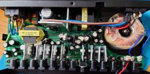
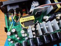
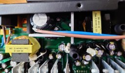
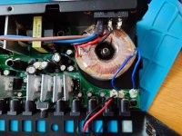
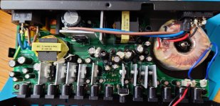
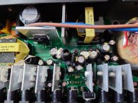
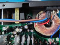
Edit: I popped it open, each output has it's own voltage regulator (or at least I assume that's what they are, huge heat sinks). I doubt 6 of those just broke at the same time, but I can't see where there could be a split between either side (first 6 do not work, the other 6 presumably work, I didn't test the AC but the other 5 work), or if they are somehow partially chained and the issue could be where the chain is. A ton of caps and diodes, no visible signs of problems.
 
Last edited:
It may be worth fixing, but I wouldn't go poking around in there until you know exactly what you are doing. There's some big caps in there that will hold a charge even when the thing isn't plugged in, so if you're aren't comfortable with mains voltages, it may be best to send that one off to the repair shop.

The CS12 is a switch mode power supply, so they aren't daisy chained. I believe there are two main transformers in there, and if you have six of the voltage regulators fried, that would indicate that you have an issues on the mains side of the board. If you do decide to try to fix it, I strongly recommend that you familiarize yourself with switch mode power supplies and the safety protocols of working with circuit boards that are connected to mains. If you want to educate yourself on switch mode power supplies, I suggest checking out some of DroneBot Workshop power supply videos on YouTube at least to get a good understanding of how they work. And then, if you can get past his quirkiness, I also recommend checking out some videos from Learn Electronics Repair. He's probably got a video on troubleshooting a power supply.
Thanks, I might give it another quick look, and maybe take the PCB out and check the underside. But if I can't find anything easily I'm not going to try anything more, because I don't want to try measuring anything while it's plugged in. I might ask for a quote to get it repaired, I suspect it's not a tough job for someone well versed and trained for something like that, but I also suspect I might just have to bite the bullet and get a new one - I think an experienced repair worker might ask for 100€ easily, and that won't really be worth it to me compared to a new one with warranty.
 
Just make sure you discharge that big cap in there before you poke around too much. If you leave it unplugged long enough it will discharge on its own, but it's always a good idea to connect a resistor across the leads for a few seconds before poking around in there. Don't use a screwdriver or pair of pliers to short the cap, that can damage the cap.

And yeah, don't poke around in there with it plugged in. Good luck.
 
90% of the time I fix a switching power supply, it's a small value electrolytic capacitor, something like 10u/50V. It's likely in the feedback loop of the switching IC. You can't tell it went bad by just looking at it. Nowadays I just look for it and replcace it right away, along with any other electrolytics that may look swollen. This process almost always fixes it.
 
Just make sure you discharge that big cap in there before you poke around too much. If you leave it unplugged long enough it will discharge on its own, but it's always a good idea to connect a resistor across the leads for a few seconds before poking around in there. Don't use a screwdriver or pair of pliers to short the cap, that can damage the cap.

And yeah, don't poke around in there with it plugged in. Good luck.
Just to clarify, the leads of the big cap? The power plug probably won't be enough? Does the size of the resistor matter much?
I'm curious.

Can you post a picture of the PCB?
I'll try to get pictures tomorrow, if for nothing else then just for curiosity.
90% of the time I fix a switching power supply, it's a small value electrolytic capacitor, something like 10u/50V. It's likely in the feedback loop of the switching IC. You can't tell it went bad by just looking at it. Nowadays I just look for it and replcace it right away, along with any other electrolytics that may look swollen. This process almost always fixes it.
From what I can tell, I can probably disregard most of the electrolytic caps - there seems to be ~3 of them for each output, and since half of them are malfunctioning, it's probably not those.

Then there's the big cap, and two smaller caps right next to it (also marked at least C5, while the output ones are c101, c201 and so on up to c1101. The ones that can't be switched to different voltages also have diodes. Then there are two rectangle transformers (I don't know the correct name), a big toroidal transformer and two quite small toroidal transformers. Plus a couple of box caps, an IC1 with a heatsink that goes to the PCB (ground layer? I think it's for using with different input voltages) and IC's for each output separately too.

So it sounds like it could be one of the smaller caps next to the big one, but I'll try to take pictures of both sides of the PCB tomorrow. None of the parts look swollen or burnt to me at all.
 
The more you overthink it, the more you're not fixing it. A cap is worth nothing even if you replace a good one, so I'd just go for it. It's very likely a cap between 2.2u and 47u, at probably 50V. There won't be much more that one or two of those on the board. Don't worry about being electrocuted if you've unplugged it more than a few minutes ago. I have never seen one that doesn't self-discharge the high V caps in a minute or so. Put a meter across the big cap if concerned.

Oh, and make sure the replacement cap is rated at 105 degrees (not 85) if you want longevity.
 
Yeah, as long as it's been a few minutes you should be good. I still drop a low value resistor across the leads just to be safe, or I read the voltage with my DMM -- better safe than sorry. And no, the value doesn't matter too much -- you just don't want to short a fully charged cap.
 
Took me a bit longer since my nephew's baptism took a bit longer yesterday.

But yeah, I don't think I'm fixing this thing. In hindsight I should have seen this coming since it was a bit too simple, but I wasn't quite expecting this:

DSC_3123.JPG

And I'll attach some other pics from the top side which show the through-hole components. I guess I could take a stab in the dark and replace the two small electrolytic caps next to the big one. I think they are these ones, not labelled on the bottom side of the PCB. I think the discoloration might just be flux, I could try measuring them from there but I doubt that would give me helpful info - maybe if one of them measures something and the other one doesn't, but being in circuit they could fool the tester.

DSC_3125~2.JPG
 

Attachments

  • DSC_3113.JPG
    DSC_3113.JPG
    341.3 KB · Views: 16
  • DSC_3116.JPG
    DSC_3116.JPG
    424.7 KB · Views: 12
  • DSC_3117.JPG
    DSC_3117.JPG
    299.3 KB · Views: 11
  • DSC_3121.JPG
    DSC_3121.JPG
    378.7 KB · Views: 11
  • DSC_3112.JPG
    DSC_3112.JPG
    314.8 KB · Views: 11
  • DSC_3119.JPG
    DSC_3119.JPG
    406.8 KB · Views: 12
  • DSC_3120.JPG
    DSC_3120.JPG
    359.4 KB · Views: 15
Yeah, tough one, I wouldn't want to call it. But those two caps you pointed out might be a good guess. For sure it won't be one of the output filter caps, so nothing close to the outputs. Also, the cap rated voltage is a good indicator. Output filter caps will be rated not that much higher than the output voltage they serve (say, 16V rating for a 9V rail). The cap that often fails is in a feedback loop, physically not far from a (yellow) transformer, and usually rated quite a bit higher than any output voltage. 10u/50V is pretty common.
 
FWIW I tried measuring both caps in circuit (which is of course not accurate, I know), and they both gave the same readings so I suspect it wasn't those caps. I tried reflowing it overall with the hot air gun, but then also when it broke it smelled like burning... So I just decided to order a new power supply and give up on this one. Thanks everyone for your help anyway!
 
Is there a bridge rectifier (4 diodes) that convert AC to DC? Maybe that went bad. Or is there a polarity protection diode or resistor that might drop the voltage a bit?
Just a thought for another place to check as well if the electrolytics don't solve it
 
Is there a bridge rectifier (4 diodes) that convert AC to DC? Maybe that went bad. Or is there a polarity protection diode or resistor that might drop the voltage a bit?
Just a thought for another place to check as well if the electrolytics don't solve it
Like I said, I already gave up on it. But I don't think I saw 4 diodes in a group (or I guess two sets of 4 diodes in a group, since half of it still works). There are diodes per output at least, not sure if there are more per half of the pedal.
 
Like I said, I already gave up on it. But I don't think I saw 4 diodes in a group (or I guess two sets of 4 diodes in a group, since half of it still works). There are diodes per output at least, not sure if there are more per half of the pedal.
Sorry I missed that you quit on it - hard to read at a sunny track meet. Weird situation with it.
 
Hello! I was meant to comment on this like a week ago at OP's request. But life happened and I had to look after someone close to me.

I intentionally purchased a CS12 with this defect and in order to fix it. Not a lot of resources online - Truetone seems to be good with warranty repairs, as that is the go to recommendation.

I found that in my case, there was a short circuit across one of the diodes on the underside of the board. I actually emailed Truetone on the hopes I could get schematics - no such luck. Very unfortunate that companies are no longer willing to give out schematics so that people can repair stuff themselves. The support person I was in contact with was actually able to give me a page of their internal troubleshooting guideline. I won't post it here as I doubt I have permission to do so, but the relevant part is as follows:

2.5 Whole output group is NG
2.5.1 Check which output group has no voltage or is abnormal (Outputs 1-6 or 7-11).
2.5.2 When the DC power is off, use a discharge resistor to discharge C1 for 5 seconds and
check whether there is any abnormality (like shortͲcircuit or low resistance) at each
output of the failed group by measuring the resistance of each DC Jack (J101 ~ J1201)
2.5.3 Measure the output diode (D101 ~ D1101) resistance of abnormal output. If its resistance is about 0~100,
replace this diode with a US1G diode (D101-601) or DO-201/HER303 (D701-1101).

(Note that this troubleshooting guide is slightly inaccurate, the AC output jack SHOULD show very low resistance, as it is connected directly to a low voltage transformer with very low DCR windings.)

After I removed the shorted diode, the output came back up, though with lots of ripple. I need to order a replacement part in my next mouser run before I actually plug a pedal into it!
Thank you! I also used the contact form to contact them, but they never replied to me - which is fine, as my unit is out of warranty by multiple years. But it would have been nice to hear something back.

Anyway, I'll give those steps a try! Did I get it right, one faulty output diode (of a single output) makes the whole group misbehave?
 
Yep! One bad diode brough down the same output group that you're having issues with. Hopefully there's nothing else wrong, but i suspect the culprit is one of those diodes. You can literally remove it and you should see the voltage come back up to 9 point something. With a load of ripple mind you, like I said, I wouldn't actually plug a pedal into that 😂
 
Yep! One bad diode brough down the same output group that you're having issues with. Hopefully there's nothing else wrong, but i suspect the culprit is one of those diodes. You can literally remove it and you should see the voltage come back up to 9 point something. With a load of ripple mind you, like I said, I wouldn't actually plug a pedal into that 😂
Thanks, I'll test that out at some point. I already have a new power supply so I'm in no rush, but it would be nice to fix it.
 
Back
Top