

You are using an out of date browser. It may not display this or other websites correctly.
You should upgrade or use an alternative browser.
You should upgrade or use an alternative browser.
A simple Relay Bypass
- Thread starter Chuck D. Bones
- Start date
Chuck D. Bones
Circuit Wizard
No worries, you get credit for being on-topic and not posting any memes.
if you want to reliably drive a latching relay, use a microcontroller.
Here is one such example.
")
PedalPCB has a latching relay bypass board that uses an NE555 (instead of a microcontroller) to maintain state and react to momentary switch presses. I think the NE555 could be replaced with a couple inverters (e.g. cd40106 or 74hc14) with a circuit like this. I have breadboarded this, and it certainly works for toggling between two states with a momentary switch. The advantage is dramatically reduced power consumption (the disadvantage is a physically larger chip).
With the single-coil latching relay, you need the ability to produce a bi-directional current pulses (pulse one way for set, pulse the other for reset). That is easily done with two pins of a microcontroller (that have the appropriate current sourcing/sinking capability and builtin protection from coil flyback). The way it's done with the PedalPCB bypass is to use a capacitor in series with the relay coil. While DC won't pass through the capacitor, there will be a current pulse generated by it being charged or discharged depending on which transistor is open (either the PNP to ground or the NPN to VCC).
My question: assume that Q2's collector is attached to the relay coil's design voltage (5v in the case of the TQ2-L-5V, which also happens to be a good supply voltage for inverter ICs). Could we then remove the series capacitor C3, and replace R4 with a series capacitor (i.e. in series with the base of Q1)? And additionally add a resistor to ground between transistor gate and the series capacitor. The goals being (1) to activate the relay coil with it's design voltage, instead of the approximately-correct voltage from the cap charge/discharge current, and (2) get away with a smaller capacitor (hopefully small enough to use film or ceramic) since we only need to drive the transistor base?
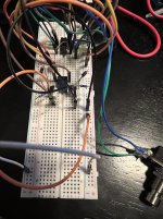
I have bread-boarded something conceptually similar, though I'm using a two coil latching relay, and MOSFETs instead of BJTs - but the main idea from my question is the same: using a series capacitors to generate a pulse for the FET gates (and the FETS do the "heavy lifting" of current sinking). It works as expected on the breadboard. Assuming this isn't a flawed design for some reasons that I'm unaware of, for simple on/off relay bypass, it has a lot of advantages: micro-amp current consumption (except when switching of course), simple circuit, uses cheap, commodity, current-production components. Schematic attached.
Attachments
Chuck D. Bones
Circuit Wizard
You might want to try a CD4013 type D flip-flop. Saves some parts. But at about a buck each and free firmware, a μC is hard to beat.
We used latching relays a LOT in spacecraft because the coil current is zero 99.9% of the time and they remember their state when the power is off. 4PDT relays were a favorite because one set of contacts could be dedicated to feedback to the controller.
One more thing... you don't have to run the 40106 or 4013 from regulated +5V. They work fine on +9V. You don't need to run the relay off of regulated voltage either.
szukalski
Well-known member
For anyone following this relay, I uploaded the v2.1 of my layout:

 github.com
It's the same as v2.0 but with a smaller footprint, less height.
I have a v3.0 drawn up which lets you choose to use the LED of the main board or the relay, but it's not smaller than this one.
GitHub - szukalski/pedal-simple-relay
Contribute to szukalski/pedal-simple-relay development by creating an account on GitHub.
github.com
It's the same as v2.0 but with a smaller footprint, less height.
I have a v3.0 drawn up which lets you choose to use the LED of the main board or the relay, but it's not smaller than this one.
drgonzo1969
Well-known member
Is the SPST momentary?For anyone following this relay, I uploaded the v2.1 of my layout:
GitHub - szukalski/pedal-simple-relay
Contribute to szukalski/pedal-simple-relay development by creating an account on GitHub.
It's the same as v2.0 but with a smaller footprint, less height.
I have a v3.0 drawn up which lets you choose to use the LED of the main board or the relay, but it's not smaller than this one.
szukalski
Well-known member
Yes. You can use any mechanism to make a complete circuit.Is the SPST momentary?
Chuck D. Bones
Circuit Wizard
Stomp switch should be normally open.
Hi, could you please help with the attributes of U1(when using FTR-B4CA) on relay-v2.1-cpl.csv? Is the rotation =269.99 correct? Seems like it should be 180 based on visual inspection on JLCPCB.For anyone following this relay, I uploaded the v2.1 of my layout:
GitHub - szukalski/pedal-simple-relay
Contribute to szukalski/pedal-simple-relay development by creating an account on GitHub.
It's the same as v2.0 but with a smaller footprint, less height.
I have a v3.0 drawn up which lets you choose to use the LED of the main board or the relay, but it's not smaller than this one.
My recent Paragon build has LED pop and after all the usual trials ( LED change, Tantalum output caps, AMZ method etc) I was wondering if using Relay Bypass would eliminate/reduce it as removing the LED makes the switching dead silent.
Chuck D. Bones
Circuit Wizard
LED pop could be caused by grounding issues. The relay bypass might fix it, but without understanding why the LED pops, there is no guarantee. Maybe you want to post something in the Troubleshooting forum.
szukalski
Well-known member
I’d just remove U1 from the BoM and not worry about the rotation. It’s something you’d solder yourself.Hi, could you please help with the attributes of U1(when using FTR-B4CA) on relay-v2.1-cpl.csv? Is the rotation =269.99 correct? Seems like it should be 180 based on visual inspection on JLCPCB.
My recent Paragon build has LED pop and after all the usual trials ( LED change, Tantalum output caps, AMZ method etc) I was wondering if using Relay Bypass would eliminate/reduce it as removing the LED makes the switching dead silent.
Thanks. Sorry to hijack this thread. I posted in the Troubleshooting forum.LED pop could be caused by grounding issues. The relay bypass might fix it, but without understanding why the LED pops, there is no guarantee. Maybe you want to post something in the Troubleshooting forum.
Normally I would prefer to do exactly that but its just that I only have access to FTR-B4CA via Mouser and that's like $4 to $5 whereas if procured from LCSC via JLCPCB assembly, it's like $1. I was thinking of getting 10 to 15 done.I’d just remove U1 from the BoM and not worry about the rotation. It’s something you’d solder yourself.
Also, it appears that a slightly cheaper alternative EC2-4.5NU can b used in your circuit but the footprint seems to be different. Anyway, I will try it on a vero and see if the relay switch would actually help in my case.
Last edited:
Fama
Well-known member
I've built up two of szukalski's Simple Relay Board v1.1's now, which are identical to the original schematic here. Both have an issue where they turn automatically on when I plug in the power - any idea what could be causing that or how to fix it?
I increased C2 to 47nF in the second one because someone mentioned in an another thread it might help, but no dice.
Weirdly enough, I think a lot of other people don't have the same issue. I use a B3CA4 relay.
I increased C2 to 47nF in the second one because someone mentioned in an another thread it might help, but no dice.
Weirdly enough, I think a lot of other people don't have the same issue. I use a B3CA4 relay.
Chuck D. Bones
Circuit Wizard
If it's really that big of a deal, there are a couple of fixes.
One fix involves using the RESET pin to force the 555 into the reset state on power-up. This causes the relay to be energized immediately after power is applied. We also need to rewire the LED so it is OFF when the 555's OUTPUT pin is low.
Now we are faced with two choices:
Rewire the relay contacts so that when the relay is energized, the contacts are in bypass mode.
- OR -
Add a MOSFET to invert the relay drive. We get the added bonus of the MOSFET being able to drive more current than a 555.
The other fix is to change the capacitor values so that the capacitors "encourage" the 555 to power up in the set state. This is a bit of a balancing act because making both caps larger limits how quickly one can cycle the relay. We also have to maintain a large enough difference in the capacitor values for the circuit to work reliably.
Those of us who have tried these fixes prefer door #1, even though it adds 3 or 4 parts (3 for the reset circuit, plus a MOSFET if we go that route).
Fama
Well-known member
Oh, so it is a sort of a tradeoff? Bypass on at power on because fixing it would require multiple parts? In that case, I can live with it (or, well, I'm planning to probably sell these off, but I doubt it will be unbearable for the buyer). I wouldn't do all my pedals with these though, because that would get annoying (the way I have my equipment set up I usually power up my pedalboard each morning, although I might change that).If it's really that big of a deal, there are a couple of fixes.
One fix involves using the RESET pin to force the 555 into the reset state on power-up. This causes the relay to be energized immediately after power is applied. We also need to rewire the LED so it is OFF when the 555's OUTPUT pin is low.
Now we are faced with two choices:
Rewire the relay contacts so that when the relay is energized, the contacts are in bypass mode.
- OR -
Add a MOSFET to invert the relay drive. We get the added bonus of the MOSFET being able to drive more current than a 555.
The other fix is to change the capacitor values so that the capacitors "encourage" the 555 to power up in the set state. This is a bit of a balancing act because making both caps larger limits how quickly one can cycle the relay. We also have to maintain a large enough difference in the capacitor values for the circuit to work reliably.
Those of us who have tried these fixes prefer door #1, even though it adds 3 or 4 parts (3 for the reset circuit, plus a MOSFET if we go that route).
I was under the impression that it's not how this is supposed to work and thus figured there might be a simple fix, but if mine are working as intended, then it's fine. Thanks!