
DAJE
Well-known member
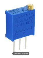
TL;DR - the title sums up what I want to do, I'm just not 100% clear on how to do it. Trimmers have 3 legs, resistors have two. What goes where?
I've made two versions of Aion's Tone Bender mk2, which has two internal bias trimmers for Q2 and Q3. Made one for me, another for a friend, and another friend now wants one. I don't want anything else from Aion right now but I do have some PedalPCB boards on the agenda so I want to use the local version, the Tone Vendor Mk2. Which has no bias trimmers. (International postage is what I want to avoid paying for twice, in case you're wondering why I can't order from both PCB makers.)
I know the 8.2k resistor is the one to replace. Any other suggestions or pointers welcome.

")
