
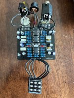
Hi kids. I have an issue with my Kliché Mini. The gain adjustment does not add a lot of overdrive sound but the pedal is stupid loud. Also, this is the 2nd I've built and the first one works as expected. Everything seems to be in place. I don't see any bleeds or unwanted connections in the solder. Any ideas? Below are pics.
You are using an out of date browser. It may not display this or other websites correctly.
You should upgrade or use an alternative browser.
You should upgrade or use an alternative browser.
Kliché Mini - Low Gain, Very Loud
- Thread starter jamie j.
- Start date
Here are my findings...Have you checked for continuity between the diodes and ground and the diodes and S4/R12/C11? I would assume the issue is with the diodes in some way, those are giving you the hard clipping and clamping your signal to ~0.3v or whatever the forward voltage of your specific diodes are before its boosted again by the 27v headroom section of the circuit.
Looking at the top of the board calling the diodes left and right:
Ground
Left: cathode has continuity to ground
Right: anode has continuity to ground
S4
No continuity to the diodes
C11
Left: cathode has continuity to C11
Right: anode has continuity to C11
R12
Left: cathode has continuity to R12
Right: anode has continuity to R12

Will do as soon as I can get back to it. I'll post the results here when done. I'm colorblind so let me make sure I'm seeing this right:Can you test this for Continuity with matching Colour circles:
View attachment 29130
Green = Left Ge anode to right Ge cathode to the - power jack (ground, i assume).
Red = the left Ge cathode to right Ge anode to the 1k (R12) resistor to S4.
Orange = 390 cap (C5) to the 1 lug of the dual gang gain pot.
OK. I was wrong earlier about the S4. I did all of the color testing and all had continuity. Not sure how I screwed up the S4/diodes earlier. They do have continuity the way you have the colors mapped out. So, all of that seems good.Yep, It could be damage from S4 trace to right side of R12 ????
giovanni
Well-known member
Did you audio probe it? Do you have a scope?OK. I was wrong earlier about the S4. I did all of the color testing and all had continuity. Not sure how I screwed up the S4/diodes earlier. They do have continuity the way you have the colors mapped out. So, all of that seems good.
benny_profane
Well-known member
Did you try swapping the diodes out? You've just confirmed that the traces are intact. You could even test the diodes by pulling one leg and performing a diode test with the multimeter. They won't test in circuit, though.
I tested for continuity with the MM. I do not own an audio probe. I do own a scope. I’m assuming that since the audio signal does not die that the audio probe/scope won’t tell me much. But I’m not well versed in the scope so my assumption may be incorrect.Did you audio probe it? Do you have a scope?
I have not swapped the diodes yet but I can. I did a test with the MM and it seemed to read then fine in the board. When I do a diode test it always beeps and gives me a value. It was the same as the working pedal’s diodes.Did you try swapping the diodes out? You've just confirmed that the traces are intact. You could even test the diodes by pulling one leg and performing a diode test with the multimeter. They won't test in circuit, though.
giovanni
Well-known member
You may be able to verify the clipping with a scope since the symptoms seem to point to an issue with that. Or better, you can compare the signal at various points in the circuit with your working unit. The scope will tell you a lot. You do need a probe to use it, but that’s a really easy build.I tested for continuity with the MM. I do not own an audio probe. I do own a scope. I’m assuming that since the audio signal does not die that the audio probe/scope won’t tell me much. But I’m not well versed in the scope so my assumption may be incorrect.
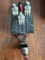
It came with probes. It’s currently connected to another pedal I’m building. I tried my hand at hand wiring without a PCB. Using a pad board. It’s a work in progress.You may be able to verify the clipping with a scope since the symptoms seem to point to an issue with that. Or better, you can compare the signal at various points in the circuit with your working unit. The scope will tell you a lot. You do need a probe to use it, but that’s a really easy build.

What behaviour are you seeing from the gain control? The gain on this does 2 things. It increases the gain (which should introduce some dirt). It also pans from an all clean signal to an all dirt signal (not that this ever gets really dirty). It is possible therefore to have the dirt part of the circuit working perfectly, but not get any dirty signal if the other half of the gain pot is not working properly
The issue is the gain produces very little overdrive and mostly volume. It does not pan from all clean to all dirty. Turned all the way up, there is a tiny bit of overdrive and a lot of volume. The overdrive is closer to what you'd get at 9 or 10 o'clock. This is the 2nd one I've built and my first works.What behaviour are you seeing from the gain control? The gain on this does 2 things. It increases the gain (which should introduce some dirt). It also pans from an all clean signal to an all dirt signal (not that this ever gets really dirty). It is possible therefore to have the dirt part of the circuit working perfectly, but not get any dirty signal if the other half of the gain pot is not working properly
Also, I swapped out the gain pot to rule out it was the issue. With the new pot, I have the same issue.

It's 47k. It would be almost impossible for me to swap a component and not notice. I am very meticulous when I work the board. Also, it means another component would be missing a spot. There is no way not to catch that, IMHO.View attachment 29210
Its always hard for me to tell the colors on blue resistors in a picture, but is this 47k or 4.7k?
swyse
Well-known member
Looking at the schematic 4.7k would have given you the opposite problem that you have now, that red band on the 47k when compared to the diode and other resistors is surprisingly brown, but anyways...
My last guess is an issue with the switch, I tested this in simulation (albeit without the bypass network) and if S4 stays grounded you just get ridiculous clean signal boosting according to the simulation. Green is signal at grounded diodes, blue is the clean signal from the other branches before it goes into the next gain stage (u3 on my picture) and then red is node Vtone, before the volume control, with the multiple lines representing position of the gain control. So if my simulation is to be believed then maybe check that the switch is switching correctly on the S4 half and if it is then I don't know what else you can do but check continuity with each component in the clipping section and compare voltages with your working unit.

My last guess is an issue with the switch, I tested this in simulation (albeit without the bypass network) and if S4 stays grounded you just get ridiculous clean signal boosting according to the simulation. Green is signal at grounded diodes, blue is the clean signal from the other branches before it goes into the next gain stage (u3 on my picture) and then red is node Vtone, before the volume control, with the multiple lines representing position of the gain control. So if my simulation is to be believed then maybe check that the switch is switching correctly on the S4 half and if it is then I don't know what else you can do but check continuity with each component in the clipping section and compare voltages with your working unit.
Should I check my S4 for continuity with ground? Or, are you saying that the S4 should be disconnect from ground with the foot switch engaged? I can check either. I'd need to know what S4 is connected to on the foot switch but if the trace is on the underside I won't be able to follow it b/c of the switch.Looking at the schematic 4.7k would have given you the opposite problem that you have now, that red band on the 47k when compared to the diode and other resistors is surprisingly brown, but anyways...
My last guess is an issue with the switch, I tested this in simulation (albeit without the bypass network) and if S4 stays grounded you just get ridiculous clean signal boosting according to the simulation. Green is signal at grounded diodes, blue is the clean signal from the other branches before it goes into the next gain stage (u3 on my picture) and then red is node Vtone, before the volume control, with the multiple lines representing position of the gain control. So if my simulation is to be believed then maybe check that the switch is switching correctly on the S4 half and if it is then I don't know what else you can do but check continuity with each component in the clipping section and compare voltages with your working unit.
View attachment 29212
If I'm understanding correctly, here are my findings. S4 has continuity to ground when the foot switch is bypassed. When engaged, there is no continuity to ground.if S4 stays grounded you just get ridiculous clean signal boosting according to the simulation.
swyse
Well-known member
Yep, that's what I meant, If those are your findings then it sounds like the switch isn't grounding out the clipping signalIf I'm understanding correctly, here are my findings. S4 has continuity to ground when the foot switch is bypassed. When engaged, there is no continuity to ground.
Can you check to see if you have Continuity with Gain top centre solder pad B2 & R16, R17 & R18 top solder pads?OK. I was wrong earlier about the S4. I did all of the color testing and all had continuity. Not sure how I screwed up the S4/diodes earlier. They do have continuity the way you have the colors mapped out. So, all of that seems good.
Look at the PCB Continuity board I posted before for updates!

Last edited:
Similar threads
- Replies
- 0
- Views
- 144
- Replies
- 14
- Views
- 1K
- Replies
- 12
- Views
- 449
- Replies
- 1
- Views
- 145