Dan0h
Well-known member
I need help. Dumb questing but I really don’t know.
If you have two circuits that you wish to combine but they both operate on different voltages can their audio paths be intertwined in the same circuit? Is the audio portion of the circuit separate from the power section? I know this is a dumb question but it’s got me all tied in knots.
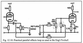
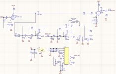
What I am trying to bread board is a tube preamp with a delay circuit in the “effects loop” of the tube preamp circuit. Coming from the first stage of a 12ax7 into the delay circuit and then out and into the second stage of the 12ax7 with a blend pot to mix in the wet signal. In my head it can work but because the delay and the preamp circuits are running at different voltages will this cause an issue? It shouldn’t right? Pedals of all sorts of voltages are mixed and matched all the time, but can they be wired together?
My last bits of parts should arrive soon from Tayda, then I can wrap up the breadboarding just thought I would ask before I zap myself or the circuit.
The photo is not the values I intend to use but the path is.

Or am I wasting my time trying to surgically insert a delay between the two stages of a tube and would be better served just having the two circuits tided from out to in like everyone else does for two in one builds?
Thanks in advance.
If you have two circuits that you wish to combine but they both operate on different voltages can their audio paths be intertwined in the same circuit? Is the audio portion of the circuit separate from the power section? I know this is a dumb question but it’s got me all tied in knots.
What I am trying to bread board is a tube preamp with a delay circuit in the “effects loop” of the tube preamp circuit. Coming from the first stage of a 12ax7 into the delay circuit and then out and into the second stage of the 12ax7 with a blend pot to mix in the wet signal. In my head it can work but because the delay and the preamp circuits are running at different voltages will this cause an issue? It shouldn’t right? Pedals of all sorts of voltages are mixed and matched all the time, but can they be wired together?
My last bits of parts should arrive soon from Tayda, then I can wrap up the breadboarding just thought I would ask before I zap myself or the circuit.
The photo is not the values I intend to use but the path is.

Or am I wasting my time trying to surgically insert a delay between the two stages of a tube and would be better served just having the two circuits tided from out to in like everyone else does for two in one builds?
Thanks in advance.


