Relay switching question....

Willybomb

Active member
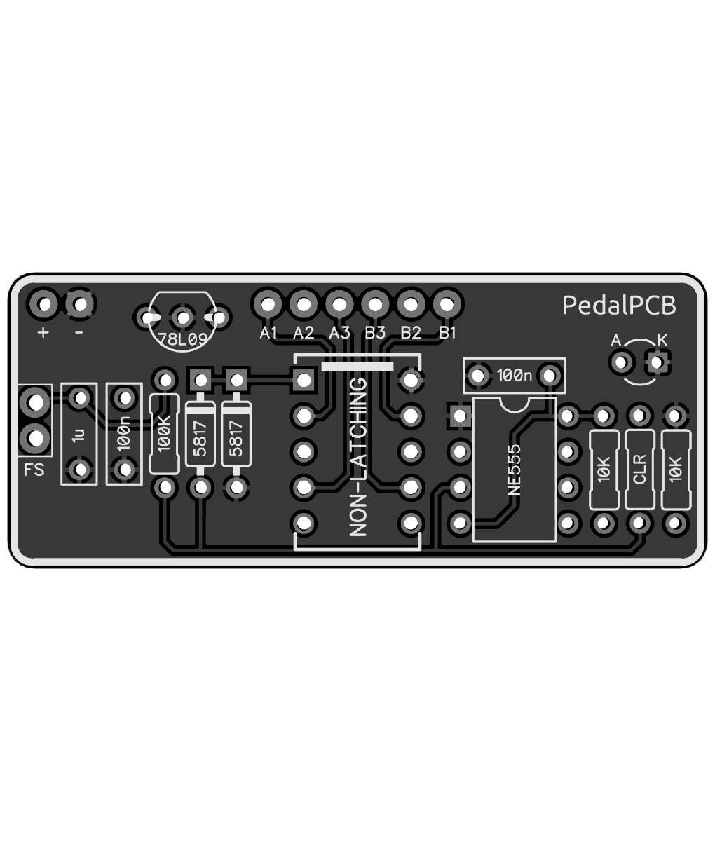
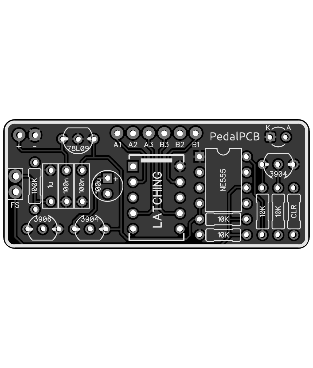
So, what I want to do is use a relay bypass to switch between two always on effects. I've worked out how to do this with Paulinthelab's relay switching here:


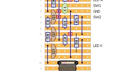
by cutting at T4 and hooking the other effect in/out along opposite sides of the t-row.

However, this layout only works on a single "pulse" to engage and then disengage. What I want is for it to also engage while the switch is held down. Can I use one of the relay pcbs here to switch between two boards - I see that they can either bypass or engage but I want to "bypass" to another effect. Is there a cut I can make on the board to enable this by wiring the "bypass" to the pins on the relay?
 
Think of it this way:

Using a 3pdt, normally lugs 1 and 7 are the effect in/out, and 3 gets connected to 9 for a bypass, or some sort of variation on this. But, what I want to do is connect a second effect to 3 and 9 instead of a bypass so I'd be switching between them. There's no stacking.

I can do this with a 3pdt and include a bicolour led, easy. I can do it with the vero layout above, BUT, I want to be able to switch to the second effect only while the switch is held down as well as a single stomp. The bypass pcbs allow for this, but only between a single effect and bypass, not between two effects. Standard mode would be fine, IF I could have the second effect instead of bypass.
 
Did you watch that video? Instant switching mode allows you to go between two effects and retains the hold function.

I’m interpreting your request as wanting to switch between two always-on circuits AND be able to press+hold for temporary enable. If that’s the case, the CTRL pad on the updated intelligent relay bypass allows you to do that. You’d need two boards/SPST switches to accomplish that.

Otherwise, I’m still not understanding what you’re asking.
That's pretty much it, but off one footswitch.
 
Thanks. I'm not fussed about the LED, I'm happy for it to be on only when the dirty effect is engaged.

It will probably be addressed in the documentation, but how would I wire it up for a second effect to switch to?
 
You'd connect pin A2 to the input jack, B2 to the output jack.

A1 to FX1 input, A3 to FX2 input.

B1 to FX1 output, B3 to FX2 output.


Because of the nature of latching/unlatching relays the two modules start up in different states.

The Latching version starts up with A2/A3 and B2/B3 connected, so you'd want to connect your "default power on" effect to A3 / B3.
The Non-Latching version is the opposite, so you'd want to connect your "default power on" effect to A1 / B1.

I can draw a diagram if this is confusing, it's fairly straightforward.

Otherwise the modules both behave exactly the same, the difference is the type of relays they're designed for.


They're here now and verified, I'll make them available Wednesday as soon as I get back home.
 
78L09 is correct. The 555 output is lower than it's VCC (by about two volts if I recall), so at 5V it might not engage the relay.

The regulator was mainly intended for times when the pedal is powered above 9V.

Also, as Harry Klippton unfortunately recently discovered, there is no onboard polarity protection on the "Basic" modules, so you'll want to tap the supply from a point that is already protected against reverse polarity.
 
Back
Top