XC Phase (Phase 90) Issues

equinox

Member
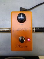
I just finalized an XC Phase pedal. I have one question and one issue. The thing is functioning appropriately and engaging/disengaging.

The issue I have is that there is a loud audible "POP" when engaged (not when disengaging)! I have an actual MXR CSP026 74 Vintage MXR Phase 90 I purchased in 2020. That thing sounds killer and sweet and there is absolutely no popping when engaging or disengaging, so wondering what's up?!? I've built literally hundreds of pedals and was a tech and sr. tech when i started my career in engineering almost 30 years ago, so it's built right and has to do with something else.

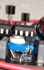
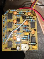
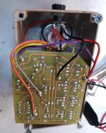
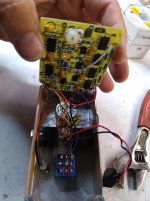
This must be a Rev. 1 board, as yes, Q1-Q4 are installed backward from the original silk screen, fyi.

The second thing and question is how to set the trimmer? I know a lot of information just says set it in the middle of the phasing, but I'm wondering if there is something a little more definitive, like....if 9.00VDC input, set drain at 4.50VDC exactly OR to via pinX and monitor on oscilloscope until just before clipping on the screen....both would be pretty definitive.

Since I have an actual one, I'm wondering if there is anything I can look for on it, like a voltage at a certain pin or something on the oscilloscope?? Then I can copy the same thing I'm seeing on the actual unit, to the clone??!?

Also, when making these modulate components like Phasers or Choruses, the JFETs (2N5952) need to be matched. To ensure they are, what is the best method to test them??

PLEASE ADVISE. Thanks in advance.
 
Last edited:
Also, when making these modulate components like Phasers or Choruses, the JFETs (2N5952) need to be matched. To ensure they are, what is the best method to test them??
A transistor tester that measures the gate-source voltage needed to turn the device off (vgs-off).

Some folks like the R.G. Keen method, which is a simple DIY measurement comparison circuit.

I use a Peak DCAPro.

Hope this helps.
 
A transistor tester that measures the gate-source voltage needed to turn the device off (vgs-off).

Some folks like the R.G. Keen method, which is a simple DIY measurement comparison circuit.

I use a Peak DCAPro.

Hope this helps.
So you're using the Atlas DCA75 - Atlas DCA75 Meter

Yeah, I have 3 or 4 of the Atlas meters and love them. I don't have the DCA75.

It looks like there is an "Improved JFET Matcher" which measures Vp Idss and Vgs out there originally from RG Keen - Greatly Improved JFET Matcher

This will help ensure the components are matched. Now, is there a tuning process defined, voltage, or something we're supposed to see on the scope to know when we have the circuit tuned perfectly and getting that sweet sound??

In regard to the "popping", need to understand what is causing this and if anything with Rev. 1 boards??
 
  • Like
Reactions: fig
Switch popping is the nature of the beast with true bypass circuits. Your vintage unit isn’t true bypass so, that’s why you’re not getting switch pop. There are things you can do to try and mitigate it here. http://www.geofex.com/article_folders/bypass/bypass.htm

There’s not really a true scientific way to bias a phase 90 that I’ve read about. All of the phasers I’ve built will sound their best at different bias voltages depending on the jfets that are installed. Just adjust by ear. The best way I’ve found to bias the xc phaser is, Set your speed at noon, your switches to 4 stage and added feedback. Adjust your trimmer to the widest and cleanest phase as you play through it.
 
Thanks for the link! Only problem is...it appears the original MXR CSP026 '74 Vintage Phase 90 seems to be a true bypass of a sort and doesn't "Pop"!!

I'm attaching the original schematic from ElectroSmash. It doesn't show the switching, but shows the different section of the pedal and I do not there isn't even the 1M pull-down resistor, like in the Pedal PCB!

The original is wired up like in your link with the "Simple SPDT Bypassing"! They suggest it "sucks tone", but this is how all of my 1974-1980 vintage MXRs are actually wired up!! On the '74 reissue, I'm attaching photos so you can see how hooked up, but has three wires (yellow-FX/Jack Input, violet-FX Output, and blue-Output Jack) on the switch!

I wired the PedalPCB up like the attached using the 3PDT and True Bypassing the pedal when disconnected shunting the Input to ground. Now, again, the PedalPCB does have the 1M pull-down resistor off of the FX INput.

I would have thought the 1M pull-down would help with "pop", but again, the vintage just has the Simple SPDT bypass and no 1M pull-down!

I wonder what is up and thinking maybe wiring it up to just a simple SPDT and see what happens?? Maybe try removing and adding 1M pull-down resistor to see effect.

Really perplexed that it's doing it as one would think the way I've wired it up would be more better solution and again the article called it a Tone Sucker!! :O

I recorded an A-B between the two so you could actually see and hear it and the difference between the two. It's late though, so won't be uploading until tomorrow.
 

Attachments

  • IMG_20210110_151939275.jpg
    IMG_20210110_151939275.jpg
    510.8 KB · Views: 16
  • IMG_20210110_152033032.jpg
    IMG_20210110_152033032.jpg
    555.4 KB · Views: 13
  • IMG_20210110_153527060.jpg
    IMG_20210110_153527060.jpg
    610.5 KB · Views: 15
  • IMG_20210110_153549624.jpg
    IMG_20210110_153549624.jpg
    348.9 KB · Views: 16
  • MXR Phase 90 Script - Schematic.jpg
    MXR Phase 90 Script - Schematic.jpg
    194.4 KB · Views: 16
  • Script Phaze 90.jpg
    Script Phaze 90.jpg
    338.6 KB · Views: 16
  • Simple SPDT.jpg
    Simple SPDT.jpg
    17.1 KB · Views: 19
Your MXR Phase is a period correct reissue therefore it's not true bypass (and it only runs on batteries).
As for the tone suck, it's easy to test. Some people have also complained that it bleeds a bit of phasing on bypass and that it's noisy. Grain of salt with these reports, as always.

My Dunlop Fuzz Faces are true bypass and they only run on batteries but they have no pulldown resistor and they don't pop. Couldn't tell you now if they ground the board input on bypass. I'm several countries away from them right now.

I built a true bypass pedal with no pulldown resistor and no grounding of the effect input on bypass and it pops a bit. Only battery operated.

I also have several standard pedals that still pop despite the above workarounds. Sometimes it's the LED that stores some voltage.
The switches in my Unpleasant Surprise pop like crazy, I can't toggle them when the pedal is on.
 
How is it not True Bypass when it was originally hooked up, again, like the SPDT bypass I posted above with pictures showing the footswitch and the 3 wires going to it, just like the "Simple SPDT" illustration, no relay or transistor switch, etc.?!??

I have FIVE Phasers on the bench as I said, one original, and 4 clone PCBs. The original MXR sounds lush and significantly better and the best one on the bench!!

Yes, originally it was battery only, but since I got it and as and has been current, I made a couple modification....I added a DC power jack, an LED indicator, and 3PDT True Bypass switch! The switch is still wired as previous with the Blue going to the center and switching between the Violet and Yellow wires! The LED is run in parallel to the pedal, so it is unaffected. The positive goes to the plate of the LED thru a current limiting resistor and the cathode goes to the switch when in "active" mode. A black wire is run from the negative terminal of the DC jack to the center of the switch.

In this current configuration, I am getting no "pop". The tone is lush and the best sounding I have, and there is no audible "tone suck" that I am precieving!!

Again, I'll post a video clip in moments so you can see and hear what I am experiencing.
 

Attachments

  • IMG_20210110_173643324.jpg
    IMG_20210110_173643324.jpg
    291.7 KB · Views: 14
  • IMG_20210110_173649992.jpg
    IMG_20210110_173649992.jpg
    280.7 KB · Views: 12
  • IMG_20210713_133205595.jpg
    IMG_20210713_133205595.jpg
    138.7 KB · Views: 14
  • IMG_20210713_133210973.jpg
    IMG_20210713_133210973.jpg
    134 KB · Views: 15
Here is a pic of the PedalPCB XD Phase build as well as link to the video comparing the original MXR pedal to the PedalPCB. Sounds amazing and there is pop in the MXR. PedalPCB unit is popping thru the speaker when active, no pop when disengaging.

Video - MXR Phase 90 to Pedal PCB Comparison
 

Attachments

  • IMG_20221226_212029795.jpg
    IMG_20221226_212029795.jpg
    448.7 KB · Views: 25
True bypass pop can be a pain. While there are ways to make it better sometimes it's unavoidable. I have one pedal in particular I had to use a 25k ledr to stop the rush of current from the LED when turning on. The MXR you have could just be a good sounding one🤷
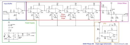
. Setting bias on a phaser is about symmetry. You can set it by ear to what YOU feel gives the most lush sound. I prefer to have a visual and audible test. Get a cheap Amazon oscilloscope and see what you are hearing. You want the same symmetry in the top half of the wave form as the bottom, smooth sine wave. Having a set number for the jfets is not logical in this circuit as tolerance of all parts and the jfet specs will be soooo different between any two units, it's not like setting the clock frequency of a BBD to a set number. As for matching the jfets, the RG Keen article linked above is the diy standard for these circuits. Sometimes a build just doesn't stack up to a really great unit, nature of the beast, but I wouldn't dismiss the advice of the people above, they have built the unit and have given sound advice.
 
Phasers aren’t prone to switch popping like delays. Leaky caps can cause that. Did you check all of your components for correct value and orientation?
 
Thanks guys. I'm reading and listening.

Doesn't sound like it should be popping! So, I'll have to dig in.

I don't want any issues with any of my builds, so use all virgin NEW components, previously Mouser, I now use Tayda exclusively unless I have a hard time getting a part and have to go elsewhere. Yes, all components confirmed and should have a set of matched JFETs if my improved JFET tester is working right. Yes, I agree...I'm not an "ear" kinda guy and like to see data and something tangible. I don't have to get a meter. I have a Fluke 123, just need to know where to monitor it, off the input? or certain pin on something??

Sometimes poor quality switches can do it and "bounce". These are good soft latching ones, so not a lot of pop just from the foot switch.

I'm in the middle of something right now, but when I break away, I'm going to try a few things, like going back to the MXR switching.
I do get pops when using the two switches, but not with the foot switch. To me, the best sound is with both toggles facing inwards. I’m not sure offhand which those are, as my friend has the pedal right now.

This is a pic of my guts. The trimmer is actually set at about 10:00-11:00

The only thing I notice that’s different between ours is the grounds to the pedal are opposite. Doubt it makes a difference, I don’t know.

8C563196-69FD-4CEB-970E-CF9FF03DF915.jpeg
 
Last edited:
Aww...Mammoth. Miss them. Great company and used to use them all the time. Shame they went under.

Well, I see you used Tantalum up on top and a Bourns trimmer! I dont see much of a difference in the True Bypass or grounds.

I'll check on "popping" when I turn the switches when I get a chance to check it out later.

I HATE that shitty trimmer from Tayda. I thought all they had until I did a search yesterday in fact, but instead of "trimmer", I just put in "3362" and all the Bourns came up!! I was like wtf? Wish I had known about that or done it previously. Looking to swap out ANY pedals with the shitty "TOKYO DENSHI" trimmer! I can move the trimmer on these on any time-based effects, like the Phaser and here is oscillating, then take the tool away and nothing!! Cheap junk imo!
 
Have you tried reflowing the jumper between 3PDT lugs 1 and 6 the reason I ask is

I built a copy of the '74 phase 90 on an etched board which popped, so added a 1M input pulldown still popped then tried one on the output still popped eventually put the link on the 3PDT and the pop was gone

I've also had no bypass signal using a slightly thicker jumper where the solder joints looked perfectly good, reflowed the joints and bypass worked, so always worth a quick reflow even if your joints look like the fabled Hersheys kisses
 
I looked at the board today. I reviewed the solder joints and found a couple not to my liking, so took care of them and reflowed the entire board.
I really don't like that trimmer, soo going to wait until I get the new Bourns-type from Tayda, then see if any change. If not, I'll try changing the bypass method and to MXR and see what happens, so will probably be a couple days.

I do have a PedalPCB CE-2 Chorus clone also I built. It sounds very good and lush. However and fyi, I did note it does "pop", again when engaging (not disengaging)!! This pedal has the newer soft latching 3PDT switches also!!

Soo another thing I'll investigate is bounce and if these switches are causing the issue?!?

STAY TUNED
 

Attachments

  • IMG_20221228_214943958_2.jpg
    IMG_20221228_214943958_2.jpg
    200.4 KB · Views: 8
Ok guys. I finally had the time to delve into this...and I have a solution!!

The problem was not the switch...it was not the use of a tube amp...it was what I was thinking and had to do with the True Bypass scheme!!

Attached is an illustration I put together. The first one is the normal way "I" wire true bypass pedals and have been doing it for almost 15 years! The problem was the wire in RED which when you DISENGAGE the pedal, switches the ground from LED to the FX input shunting it to ground and the reason is to quiet the pedal and eliminate any crosstalk and bleeding of the signal.

For whatever reason, this was causing the "POP" when ENGAGED (not when disengaging)!

The solution was to remove the one wire in Red! I tried 2 different bypass schemes. The popping issue when I went back was happening on both the PedalPCB Phaser and Chorus! I wired one up like Bypass 1 scheme and one like the Bypass 2 scheme (which is more traditional of MXR. BOTH worked! I'm not sure if any benefits or cons of one or the other. I will be investigating more into that tomorrow for "final" arrangement, but wanted to pass this along and as I was able to eliminate the issue and make the pedal absolutely quiet with engaging or disengaging!

One other thing I will pass along guys is that there are MODs out there to add a "Rate" LED to modulated effects like Phasers or Choruses. The Pedal PCB CE-2 clone already has this integrated by Buggs, but the XC Phaser does not. I was able to add this feature as I did in a Phaser many moons ago on an old Phaser clone I built up a long time ago! To do this, I simply added an LED between what is Leg 3 of the rate potentiometer and ground! I attached the anode (+) to a 10k resistor and the resistor to Leg 3. The Cathode (-), just goes to ground. That's It!!

The optimum location for this is at the top of the pedal on the same side as Leg 3 (see illustration)!

I hope this helps some folks and if any questions, comments, or concerns....please feel free to leave feedback.

Happy New Year to All!!

note: the pedal photo was BEFORE I replaced that cheap trimer with the Bourns 3362.
 

Attachments

  • 3PDT.png
    3PDT.png
    27.1 KB · Views: 37
  • Phaser Setup.png
    Phaser Setup.png
    1.3 MB · Views: 37
Ok guys. I finally had the time to delve into this...and I have a solution!!

The problem was not the switch...it was not the use of a tube amp...it was what I was thinking and had to do with the True Bypass scheme!!

Attached is an illustration I put together. The first one is the normal way "I" wire true bypass pedals and have been doing it for almost 15 years! The problem was the wire in RED which when you DISENGAGE the pedal, switches the ground from LED to the FX input shunting it to ground and the reason is to quiet the pedal and eliminate any crosstalk and bleeding of the signal.

For whatever reason, this was causing the "POP" when ENGAGED (not when disengaging)!

The solution was to remove the one wire in Red! I tried 2 different bypass schemes. The popping issue when I went back was happening on both the PedalPCB Phaser and Chorus! I wired one up like Bypass 1 scheme and one like the Bypass 2 scheme (which is more traditional of MXR. BOTH worked! I'm not sure if any benefits or cons of one or the other. I will be investigating more into that tomorrow for "final" arrangement, but wanted to pass this along and as I was able to eliminate the issue and make the pedal absolutely quiet with engaging or disengaging!

One other thing I will pass along guys is that there are MODs out there to add a "Rate" LED to modulated effects like Phasers or Choruses. The Pedal PCB CE-2 clone already has this integrated by Buggs, but the XC Phaser does not. I was able to add this feature as I did in a Phaser many moons ago on an old Phaser clone I built up a long time ago! To do this, I simply added an LED between what is Leg 3 of the rate potentiometer and ground! I attached the anode (+) to a 10k resistor and the resistor to Leg 3. The Cathode (-), just goes to ground. That's It!!

The optimum location for this is at the top of the pedal on the same side as Leg 3 (see illustration)!

I hope this helps some folks and if any questions, comments, or concerns....please feel free to leave feedback.

Happy New Year to All!!

note: the pedal photo was BEFORE I replaced that cheap trimer with the Bourns 3362.
Awesomeness- glad you figured it out. I’m going to get it back from my friend and add that rate led. And see if he’s having any popping issues. Nice work!!
 
Back
Top