Inductor Board Connections

I know there have been several treads in reference to how to connect and inductor or transformer primaries to the universal pads on the PCB and am familiar with the connections.

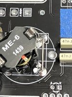
I’m working on a Mystery Machine and there seems to be no connections between the upper set of 4 holes/pads and the lower set of 3 holes/pads on the same side. How can this be considering you can use any of these pads for one side of the coil connection?

What am I missing?
 
Whatever is used there, be it one side (the primary of a 42TM023) of a transformer or an inductor (coil / Fasel), only the top-most two pads are needed. Whichever is used, it just calls for a 500mH inductance.

The two large holes at the side of the inductor placement is when a 42TM023 is used, to pinch the shield tabs thru. The 3 holes at the bottom are unused - as they are only place holders for when a 42TM023 is used.

If a Fasel (wah inductor) is used, only the outer-most two of the top holes are needed.
 
@Cybercow is correct.

For visual reference:

The Red and Green pads are the only pads that make an electrical connection.

If you're using a two-terminal inductor, install one lead into any of the red pads, the other lead into any of the green pads.

If you're using a four-terminal transformer, install one lead of the primary into any of the red pads, the other lead of the primary into any of the green pads.

All other pads are for structural support and to accommodate the unused secondary pads of a transformer


1670379948337.png
 
I’m using a Mammoth ME-6 580 mh inductor. It only has 2 pins and the spacing is too wide to fit between the top left and right pads.
 
@Cybercow is correct.

For visual reference:

The Red and Green pads are the only pads that make an electrical connection.

If you're using a two-terminal inductor, install one lead into any of the red pads, the other lead into any of the green pads.

If you're using a four-terminal transformer, install one lead of the primary into any of the red pads, the other lead of the primary into any of the green pads.

All other pads are for structural support and to accommodate the unused secondary pads of a transformer


View attachment 37484
I understand now. Because on the spacing on the inductor I have, I may need to use one of the lower pads and run a jumper to the corresponding upper pads.
 
For reference, the spacing between the 2 pins on the Mammoth ME-6 inductor is 15 mm.

Thanks to Cybercow and Robert for the help and clarification.(y)
 
Last edited:
Was looking for parts for a wah project and saw this from Dunlop, this is the wholesale price. Seems a bit steep, is this just unobtainium?
1672377742091.png

-------------------------------------------- 1672377808305.png


1672378054459.png
 
Personally I think the ME-6 transformer performs very similar to the "near-mythical" Dunlop inductors. I've got a "roll yer own" kit I wanted to give a go as well (ironically, the DIY cost is greater than buying a ready-made).

 
For reference, the spacing between the 2 pins on the Mammoth ME-6 inductor is 15 cm.

Thanks to Cybercow and Robert for the help and clarification.(y)
That's a HUGE gap on that pin-spacing of your ME-6!
Why, I bet the entire PCB doesn't measure 15cm across or diagonally.


Joking about mm-measurements aside, I'm glad I saw this thread! (Still yet to build my Conqueror)

I used the lower pin-pads in my Station-Wah build for an ME-6 as there is continuity between the upper & lower LEFT pads, and respectively between the upper and lower RIGHT pads.

I thought I'd DL'd the following diagram from another thread, but didn't. So it took me a while to find the relevant (Conqueror) thread :

**CONQUEROR**
1623701177032-png.12682


The above is how the Station Wah is, too, so I thought the above would be what's used for any PedalPCB Fasel-inductor/Transformer build.


Here's some interesting info, and a great pic by Fig of several kinds of inductors:


I'm cross posting info from this thread to the Transformer/Inductor Project-List thread.
 
Back
Top