SOLVED Gain pot not working. Help please.

neiltheseal

Active member
Hi everyone.

I'm new here and relatively new to making pedals.

I just put together the Aion FX Sapphire (Blues driver standard not the galaxie mod) and am having issues with the gain pot. The issue is that it does not work at all.
The pedal works and all of the other pots work fine but there is absolutely no gain and the pot does nothing. Here is a video of what I mean.

Does anybody have an Idea why this might be?

One potentially obvious solution would be the pot itself. As the build docs (link here) indicate a dual gang right angled pot, but I could not find one of these so just used a non right-angled one and used wires to connect to the PCB. Although with an audio probe all 6 pins of the pot have an audio signal.

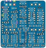
Here are some pics of the inside of the pedal and here is a pic of the schematic with my audio probe tracing. I did not completely audio probe the whole circuit as clearly it makes a sound, however I tried to look around the gain area to see where might be a problem and I am stumped.


Thanks in advance!
 
Edit : I just noticed you soldered the adaptors legs on the sockets. You are supposed to fit your transistors in the sockets without solder. The legs you chose for your adaptors are probably too large to fit in sockets, I think I recognize them and had a similar issue. This way there might be a bad connection. I would change all adaptors legs for thinner ones that can fit sockets, and with a desoldering pump, I'd try to clean or replace all sockets.
Yeah they kept popping out so I soldered them in. They were what tayda recommended. Guess I’ll try to replace them.

I don’t really need sockets right? Can just solder straight onto the pcb?
 
I don’t really need sockets right? Can just solder straight onto the pcb?
I wouldn't do that, in case your adaptors are oriented the wrong way. If you really have to do such radical and final choice, first make sure they really are oriented correctly, following schematics, with a multimeter on continuity mod. Make sure Source and Gate are connected to the right component on your build.


Moreover, with sockets you will be able to try other JFET, like 2sk117 or J201, etc.
 
Can you test for Continuity with matching colour circles.
R19 should be one or the other?
The only reason for a resistor at R20 should be 510k if you use a 500k Dual Potentiometer!
View attachment 41252
Thanks for this image. Very helpful. There is continuity between all of those matching colour circles as it currently is with the resistors. I’ll aim for that when I put a pot back there.

I used 500k so I think having r20 and r9 is correct,
 
I wouldn't do that, in case your adaptors are oriented the wrong way. If you really have to do such radical and final choice, first make sure they really are oriented correctly, following schematics, with a multimeter on continuity mod. Make sure Source and Gate are connected to the right component on your build.


Moreover, with sockets you will be able to try other JFET, like 2sk117 or J201, etc.
Thanks for providing this. This might be the issue.

When checking continuity it seems the drain and source are flipped!

I feel a bit silly. I assumed since the jfet shape matched the pads on the adapter it would just work.

Guess I’ll remove the jfet as you said and replace the legs. Hopefully I can bend the drain and source into the right holes!
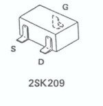
It looks confusing but jfets have been provided with 2 pinouts, D G S from the left, G S D in the Outline Transistor.

Untitled-1.jpg
 
hopefully I can bend the drain and source into the right holes
I little piece of plastic (from a wire for exemple) can be useful around the bent leg of the transistor, so it doesn't touch an other leg and make a short.

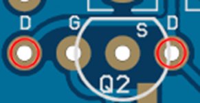
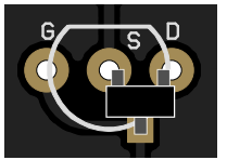
Please note that you didn't really need adaptors on this board. I soldered my smd transistors directly on the pads. On these smd transistors, one side have one leg only (Gate), this leg goes on the pcb's square pad (the pad without hole). The two other legs should be soldered on their two respective pads in front of it, those with holes. This way you can't be wrong. Edit : With your multimeter you can check continuity between smd transistors's legs and these pads to make sure they are correctly oriented. Might be easier.

What is done is done, I am just mentioning it for your next builds.
 
Last edited:
I little piece of plastic (from a wire for exemple) can be useful around the bent leg of the transistor, so it doesn't touch an other leg and make a short.

Please note that you didn't really need adaptors on this board. I soldered my smd transistors directly on the pads. On these smd transistors, one side have one leg only (Gate), this leg goes on the pcb's square pad (the pad without hole). The two other legs should be soldered on their two respective pads in front of it, those with holes. This way you can't be wrong. Edit : With your multimeter you can check continuity between smd transistors's legs and these pads to make sure they are correctly oriented. Might be easier.

What is done is done, I am just mentioning it for your next builds.

I have just never smd soldered before so was a little nervous. Was easier than I had expected but I had hoped there was more room for error with adaptors...

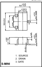
The issue seems to be that the drain and source on the PCB (and adaptor) is backwards to what is shown on the data sheet.

As you see, below is a picture of the build docs, and as you said the gate is the square pad. However drain and source are flipped on the datasheet unless I am reading it incorrectly. Could this be the issue?
 

Attachments

  • Screen Shot 2023-01-31 at 10.59.47 am.png
    Screen Shot 2023-01-31 at 10.59.47 am.png
    18.5 KB · Views: 3
  • Screen Shot 2023-01-31 at 11.01.25 am.png
    Screen Shot 2023-01-31 at 11.01.25 am.png
    25.5 KB · Views: 4
However drain and source are flipped on the datasheet unless I am reading it incorrectly. Could this be the issue?
I always have some trouble reading these datasheets. I don't think they are reversed on the pcb, though. The possible explanation is that the part is shown from below or some other angle on datasheet than on the pcb.

I just opened my Sapphire build to make sure, and yes I used the pads in front of the square one. With 2SK209 too.
 
Last edited:
Hi everyone.

I'm new here and relatively new to making pedals.

I just put together the Aion FX Sapphire (Blues driver standard not the galaxie mod) and am having issues with the gain pot. The issue is that it does not work at all.
The pedal works and all of the other pots work fine but there is absolutely no gain and the pot does nothing. Here is a video of what I mean.

Does anybody have an Idea why this might be?

One potentially obvious solution would be the pot itself. As the build docs (link here) indicate a dual gang right angled pot, but I could not find one of these so just used a non right-angled one and used wires to connect to the PCB. Although with an audio probe all 6 pins of the pot have an audio signal.

Here are some pics of the inside of the pedal and here is a pic of the schematic with my audio probe tracing. I did not completely audio probe the whole circuit as clearly it makes a sound, however I tried to look around the gain area to see where might be a problem and I am stumped.


Thanks in advance!
Thanks for your help everyone. I learned so much.

It turns out I put 510 ohm in r9 and r20 instead of 510k!

So embarrassed.
 
I always have some trouble reading these datasheets. I don't think they are reversed on the pcb, though. The possible explanation is that the part is shown from below or some other angle on datasheet than on the pcb.

I just opened my Sapphire build to make sure, and yes I used the pads in front of the square one. With 2SK209 too.
Hi again.

As you have built one of these I thought I’d run this by you.

Below is a video of the pedal working. Does this sound like too much hum/feedback to you?

I was sitting directly in front of the amp but it doesn’t reduce much when I move away (except for the hi pitched squeal)

 
Does this sound like too much hum/feedback to you?
This kind of noise can vary a lot, depending on the power supply, how the power supply is connected (power strip and such), the electrical environment in general...

Being very close to the amp, makes it kind of hard to tell...

Would you say it's much more noisy than your other high gain effects ?

I never felt like this circuit was noisy, but if Gain, Volume and Treble are fully CW, there will be some annoying background noise for sure. A good noisegate will definitly solve this.

I'll record something with mine, for comparison.
 
Bass at 12'
Treble fully CW
Gain at 12', then fully CW
Volume at 9' and fully CW, and 9' again...
After 1 minute, i start toggling on and off the "tight" mode : less bass and a bit more sharpness.

I found this mode on Wampler BD-2 article, at premierguitar.com


D7, D2 = D9k (sub 1N34A) in series with 1N4001
D3, D5, D6 = D9k

R13 = 1M resistor/100R on a toggleswitch
R14= 15k/8k2 on the same switch

The mod cuts some bass (R13/100R is effective getting closer to an overdrive) and some mids (R14, 8k2 get the circuit quieter, losing some density in the saturation). The switch allows to toggle from standard values, to modded values. You should try...


As you can see on the picture, it's recorded with an RC-3, so you can hear only the Sapphire.

0:20' Bass and Gain are at 12' Volume and Treble fully CW, briefly.
At 0:50' I set Volume Gain and Treble fully CW.
I use a guitar with active pickups, volume set at 12'.
 
Last edited:
Bass at 12'
Treble fully CW
Gain at 12', then fully CW
Volume at 9' and fully CW, and 9' again...
After 1 minute, i start toggling on and off the "tight" mode : less bass and a bit more sharpness.

I found this mode on Wampler BD-2 article, at premierguitar.com


D7, D2 = D9k (sub 1N34A) in series with 1N4001
D3, D5, D6 = D9k

R13 = 1M resistor/100R on a toggleswitch
R14= 15k/8k2 on the same switch

The mod cuts some bass (R13/100R is effective getting closer to an overdrive) and some mids (R14, 8k2 get the circuit quieter, losing some density in the saturation). The switch allows to toggle from standard values, to modded values. You should try...


As you can see on the picture, it's recorded with an RC-3, so you can hear only the Sapphire.

0:20' Bass and Gain are at 12' Volume and Treble fully CW, briefly.
At 0:50' I set Volume Gain and Treble fully CW.
I use a guitar with active pickups, volume set at 12'.
Thanks for this, it’s good to have some comparison.

I think the problem might me my amp or power board. Some formerly quiet pedals are noisy too.

I’ll crank mine tomorrow and see how similar mine sounds to yours.

Thanks again for your help. I learned a lot with this pedal!
 
Back
Top