Chuck D. Bones
Circuit Wizard
Here goes...
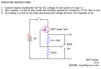
When the switch is in the up position, the gate is shorted to the source. That is the test condition for measuring Idss. The DMM is connected across the 100Ω resistor. We calculate the drain current from the voltage drop (V) across the 100Ω resistor.
Idss = V / 100Ω
When the switch is in the down position, the gate is connected to GND. The source is connected to GND thru the 1M-10M resistor. The DMM measures the voltage between gate (GND) and source. That's Vgs. The drain current, Id, flows thru the 1M-10M resistor, which causes the drain current to be very low, between a few hundred nA and a few μA, depending on the exact resistor value and Vp. That's the test condition for measuring Vp (Vgs,off). The DMM reads Vp directly. Note that Vp = -Vgs,off.