SOLVED Madbean total recall

Phil hodson

Well-known member
Morning all.

It pains me to post this here as I took my time on this one as I knew it’s a complex built. I was hoping to beat @MichaelW to a build report but we both hit problems at the same time. He got a new board and got it working. I’m persevering with mine thought as I want to know what I have done or not done!

So before I loose my patience and or my mind and start ripping things off the board I thought I would ask around on here. I know there are some very accomplished builders and some total recall experts here!

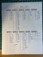
Firstly I have checked values. Cleaned the board. And started an audio probe.

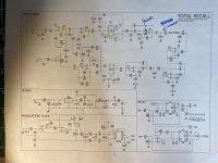
Going from the main audio schematic it’s all good. I get a squeal on pin 3 of IC3 not sure if that’s an issue.

Audio stopped at C14 so I replaced that and it’s fine now. All the way to D in. After that nothing.

I her audio on pin 3 and 4 of IC6 but no delay at all.

Looking at my voltages everything looks good apart from IC4. I get nothing at all ok the right hand side.

I also get no voltage at pin 7 of IC7. Could this be related to the issue at IC4?

My thoughts is a bridge or issue in the socket for IC4. Before I take it off does this sound like it might be the issue?

Any thoughts and suggestions very very very welcome!

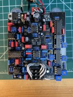
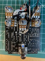
See attached pics. Can take more as required.

Phil
 

Attachments

  • 65B2A790-CED5-4BB7-A633-79965225696E.jpeg
    65B2A790-CED5-4BB7-A633-79965225696E.jpeg
    664.5 KB · Views: 52
  • 1A67EE70-D58B-405A-925F-10E01AA903E3.jpeg
    1A67EE70-D58B-405A-925F-10E01AA903E3.jpeg
    596.6 KB · Views: 55
  • 02ED75CA-7A20-4070-8D07-AE212E00919D.jpeg
    02ED75CA-7A20-4070-8D07-AE212E00919D.jpeg
    444.2 KB · Views: 47
  • 8248C752-D280-45C0-8773-09C90EE3EB8B.jpeg
    8248C752-D280-45C0-8773-09C90EE3EB8B.jpeg
    532.5 KB · Views: 53
The voltages that are off are areas to take a look at. Like IC7 pin 7, everything connected to that pin would be an area to focus on. No one likes to hear audio probe but that is next step. If you are passing signal from the output of IC6 to the input of IC7 then you know something connected to IC7 is the problem.
Also not helpful but I've never gotten to ask this and always wanted to since the first thing anyone says with a BBD pedal is ...did you get your mn3005 from a reputable source?
 
I'd recommend you post this over on the MB forum. This one is complicated, likely need some guidance from the Bean himself. You did a good job measuring and documenting everything. I think you can track down what's wrong.
I will do. Just figuring out how to post pics on there as it say they are too big :-(
 
The voltages that are off are areas to take a look at. Like IC7 pin 7, everything connected to that pin would be an area to focus on. No one likes to hear audio probe but that is next step. If you are passing signal from the output of IC6 to the input of IC7 then you know something connected to IC7 is the problem.
Also not helpful but I've never gotten to ask this and always wanted to since the first thing anyone says with a BBD pedal is ...did you get your mn3005 from a reputable source?
I was hoping you would chime in to help! ;-)
So pin 7 of IC 7 gives nothing worthwhile. Certainly not the -7.5 is asking for. Connected to pin 7 of 7 is pin 7 and 6 an 5 of IC 4 which seems to have the duff side. I get voltages down all 4 of the left of IC 4 and absolutely nothing on the right side. I have swapped that chip so so its not that at fault.
Its always good to start with the basic questions so no offence taken at all with any single ones asked. We have to start somewhere. The chips were purchased from Cabintech and I have a few of them and have swapped them around a little with no change in anything. Which is why im leaning towards an issue with IC4 somewhere.
 
This is your problem area, double check everything in this area. Pins 3 and 4 of IC6 are the output that will feed into the second half of IC 4 that handles the gain and biasing of IC7. Since the hang up is there you aren't getting the voltages/signal to pin7 which is the input of IC7.
 
Right then!
I checked the whole of that Delay section in the schematic. All the components are the correct values.
I double checked the voltages again and got the same as the pic above.
I broke out the Audio probe and went to work.
I have audio at R39, Bias 1, R40, IC6 pins 3, 4 and 7. Also at R41, R42, C33, R43 and the XS and XR pads. Also at Gain1 and R46.
I don't have any audio at R45, Bias 2, IC4 pins 5, 6 or 7. And also none at IC7 pins 3, 4 or 7
Over to you!???
 
I'm not sure off the top of my head why that one spot is not working, I've never seen half an opamp drop out. I suggest doing with John Said.
I'd recommend you post this over on the MB forum. This one is complicated, likely need some guidance from the Bean himself. You did a good job measuring and documenting everything. I think you can track down what's wrong.
 
Thanks Chris. I have put it there too so will see what happens.
It’s weird as I have changed the chip in IC4 and it’s the same. Which is why I was wondering if it could be something as simple as a short/bridge in the IC socket I used.
 
You can test the ic socket for a bridge or if it is making contact with the PCB by taking out the ic and using your meter to see if the socket is going to the pad underneath and/or the trace next pad on top of the PCB. That would rule that out for you if you are concerned with a short.
 
You can test the ic socket for a bridge or if it is making contact with the PCB by taking out the ic and using your meter to see if the socket is going to the pad underneath and/or the trace next pad on top of the PCB. That would rule that out for you if you are concerned with a short.
What a good idea! I will go have a look at that. Save me trying to desolder it!
 
Good luck with it Phil.


As for pics... It took me a red-hot moment to realise that by clicking on the pic I wanted to post (well, clicking below it somewhere), on my phone, that suddenly I could choose between 4 options: Low-res, Med-res, Hi-res, and original (huge).
 
You can test the ic socket for a bridge or if it is making contact with the PCB by taking out the ic and using your meter to see if the socket is going to the pad underneath and/or the trace next pad on top of the PCB. That would rule that out for you if you are concerned with a short.
All sockets showed both continuity to to the trace below where its soldered and to the component next, or before in line. Balls. Thought (hoped) that might be my saving grace.
 
Some more info...
So I did what others have suggested suggested and checked all the resistors, from R9-R15 and all are good. I managed to check R15 and R14 in place and read 33K and 16K respectively

I wasn't getting correct readings from R9-R13 as im assuming, being in the circuit makes some difference to these. So I used a new one of each value and measured it correctly and then checked the code against the resistors and got 68K 24K and 51K for each of those.
I doubt replacing them would make a difference, but I can do that if anyone thinks it would help.

The Values of all the resistors in the delay line and they are all fine too.
The "Squeel" That Brian from MBP picked up in is is actually on pin 2 of IC3. Pin 1 and Pin 3 are fine. Adjusting the feedback makes no difference to the squeal. The audio on pin 3 is quieter than pin 3 but im guessing thats ok. I changed the JRC4558 out for several different ones and still the same.

I have audio on pin 3 and 4 of IC6 and also on pin 5 and 6 of IC 4. I still have absolutely no voltages on pin 5 to pin 8 on IC4!

I have NO audio at all on pin 3 or 4 of IC7.

I have swapped the MN3005 around and get the same issues.

I have continuity between IC4 pin 7 and IC7 pin 7 and R46 and Gain 1 etc. And from IC4 pin 4 and bias 2.

I have swapped out IC4 to several different JRC4558 and still the same issues.

Any thoughts from here about what else I could do? Got me totally stumped.

Thanks again.
 
Back
Top