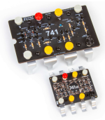
Build an Opamp from Discrete Parts

Have you tried it in a pedal? I'm building a few right now. I want to try it in a simple boost pedal like a mxr micro amp or tiger boost and see how it sounds
 
No, it's not really practical to replicate an IC with discrete parts. The transistors on a die are matched / scaled to maintain the DC balance in the circuit. The transistor junctions are all more-or-less the same temperature. We don't get that with discrete parts. Still, it will be a fun experiment so go for it!

There are better ways to realize a "discrete opamp" that does what we need it to do in a pedal with a much lower parts count. The 1st & 2nd stages of the BD-2 are one example.
 
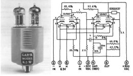
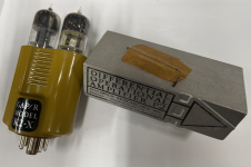
I have some of the Philbrick stuff.... cool museum pieces

opamp.png


Sporting input bias currents in the picoampere range (1x10-12), the P2 cost $220, which was 1/8 to 1/2 (my source for this one is obscure) the price of a VW Beetle at the time. The cost of building a P2 paralleled that of a cheap radio—around $10 to $15—so you can just imagine how lucrative things were in those days. The P2 dominated for 30 years, becoming obsolete only after the release of the LMC660, which now offers input bias currents at the femtoampere range (1x10-15
 
Last edited:
Very cool!

That P2 was really interesting. There's an article somewhere about it - the 3d arrangement had capacitance coupling (I believe unintentionally)- not on the schematic - and when people tried duplicating the circuit they couldn;t get it to work. It relied on the physical arrangement of parts! I guess that one way to foil reveres tracing copies!
 
Doesn't sound very robust. I wonder what the yield was at Philbrick.

I think I found the article:

"Wow! A $227 gouge. (You couldn’t call it a “rip-off” because the phrase hadn’t been invented, but perhaps that is the only reason….) Obviously, this must be a very profitable circuit. Every competitor—and many customers—realized that the P2 must cost a rather small amount to build, even allowing for a few hours of work for some special grading and matching and testing. So, some people would invest their $227 and buy a P2 and take it home and pull it apart and try to figure out how it worked. The story I heard was that one of our competitors hired a bright engineer and handed him a P2 and told him, “Figure out how they do this. Figure out how we can do it, too.” In a few days he had dismantled the circuit and drawn up the schematic. Then he analyzed it, and began experiments to be able to meet or exceed the P2’s performance. But he couldn’t get it to work well. He tried every approach, but he never could. After a full year, they gave up.

You see, it turns out there was some interaction between the input of the first RF amplifier and the output of the 4th amplifier, that made the P2 work, when you assembled the two pc boards close together. It would not work with any other layout, orientation, or circuit-assembly technique. So none of our competitors ever second-sourced the P2. And the P2 and P2A and SP2A remained profitable and popular even when the new FET-input amplifiers came along at much lower prices. It was years later before these costly and complex parametric amplifiers were truly and finally obsolete by the inexpensive monolithic Bifet amplifiers from National Semiconductor and other IC makers. Even then, the FET amplifiers could not compete when your instrument called for an op amp with a common-mode range of 50 or 200 V."

article here:
 
Back
Top