
You are using an out of date browser. It may not display this or other websites correctly.
You should upgrade or use an alternative browser.
You should upgrade or use an alternative browser.
Add momentary Octave to Parenthesis
- Thread starter befey
- Start date
Ok, so I'm thinkingSure. You'll have to deviate from the standard wiring diagram a bit, but it should work.
OCTAVE pot 1 to Relay IN
OCTAVE pot 2 to Relay OUT
OCTAVE pot 3 to BOARD OUT on the relay board
Then I can ignore the BOARD IN on the relay board.
This seems like it would bypass the octave circuit when the switch is off and send lug 3 to 2 when its active.
Ok, I'm having a bit of trouble getting my mind around how to work this. I should mention since it wasn't clear in the original question that I'm using the Parenthesis Mini pcb.Sure. You'll have to deviate from the standard wiring diagram a bit, but it should work.
The Intelligent Relay docs say that pressing the footswitch turns the effect on or off. Cool.
But holding the footswitch turns the effect OFF while it is held.
The behavior I want is to still tap for on/off. But I want to hold to momentarily turn it on.
Does the "hold" function just momentarily toggle the effect on or off depending on whether it is on or off when you hold it? That'd be fine for my purposes. If it's off, hold to momentarily turn on. If it's on, hold to momentarily turn off.
Then I think I can just wire the lugs from the Octave pot normally. But also run wires as I described above. I don't think I need the GND and SW pads on the Relay board?
I also need to add an LED for the octave part since that's not on the Mini. I saw in another thread to replace Q1 with the LED and replace the 10k resistor with some Current Limiting Resistor for my LED.
Robert
Reverse Engineer
That's correct. It'll do what you want.
Quickly pressing the footswitch and releasing will toggle ON/OFF.
Pressing and holding the footswitch will momentarily toggle ON/OFF until you release the footswitch. (if you hold while the effect is on it will momentarily bypass, if you hold while the effect is off it will momentarily activate)
Yes, you can install the LED in the place of the Base/Emitter of Q1 and change the 10K resistor to 4K7 (or whatever is appropriate for your LED).
Alright so I got everything set up. It works perfectly.
I connected
Octave pot pcb pad 1 to lug 1 of the pot AND the main "In" on the momentary switch.
Octave pot pcb pad 2 to main "Out" on the momentary switch
Octave pot lug 2 to center "Out" on the momentary switch
Octave pot pcb pad 3 to Octave pot lug 3
Connected the LED as described above and everything else according to the docs
@Robert necrothreading this for a new member ( @ozdixon ) I found over on another page….. if he is using the Intelligent relay with the standard parenthesis board for momentary octave functions I told him
Blue wire to the “in”
Green to “send”
Pink to “out”
Black to “GND”
Red to “SW”
Can you confirm that is correct please?
Blue wire to the “in”
Green to “send”
Pink to “out”
Black to “GND”
Red to “SW”
Can you confirm that is correct please?
Hey, I am going to go ahead and try this, really quick is the "send" the second "In" on the break out board? and which one of the "Out"s do I use?@Robert necrothreading this for a new member ( @ozdixon ) I found over on another page….. if he is using the Intelligent relay with the standard parenthesis board for momentary octave functions I told him
Blue wire to the “in”
Green to “send”
Pink to “out”
Black to “GND”
Red to “SW”
Can you confirm that is correct please?
I only have In,+,In,GND,SW,Out,-,Out in that order.
That’s correct, “send” is the inner “in”. Use the second “out”, the one at the end of the board next to -Hey, I am going to go ahead and try this, really quick is the "send" the second "In" on the break out board? and which one of the "Out"s do I use?
I only have In,+,In,GND,SW,Out,-,Out in that order.
kingbarnes
New member
Sorry to hop on this thread for this, but what is "SW" anyway? I have this board coming and there is no SW option. I'm not even sure how to map what they have here to a pedalpcb.com pcb with "IN", "GND", "SW" and "OUT" solder points.

- Input signal to FX PCB
- Input signal from input jack
- Ground
- Output signal from FX PCB
- LED
- Output signal to output jack
- Ground
So I got it all set up, and I'm having an insane amount of noise I can get the effect for the boost and rat, but the octave is not responsive. Do I need to power the breakout board?That’s correct, “send” is the inner “in”. Use the second “out”, the one at the end of the board next to -
Attachments
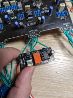
Yes, just run a second set of lines off your power jack terminalsCould I just attach it directly to the DC adapter?
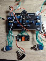
I wouldn’t necessarily blame the relay for the high noise floor. That may just be because it is a high gain circuit outside of an enclosure. Shortening your wire runs can sometimes help. Did the footswitch work as expected anyways?Hmm yeah still just an insane amount of noise. I'm going to set up a normal 3dpt and hope that fixes the issue.
No, it wasn't responsive. I even switched the momentary footswitch cords thinking I might have mixed them up. The octave pot basically doesn't nothing except when turned all the way down it cuts the effect. So I figure there might be another issue, but I need to rule out the footswitch. I am using the Op07, IDK if that would create problems.I wouldn’t necessarily blame the relay for the high noise floor. That may just be because it is a high gain circuit outside of an enclosure. Shortening your wire runs can sometimes help. Did the footswitch work as expected anyways?
In the Mini for PCBMania they have different lay out for different ICs, but the Op07 worked just fine.
Hmmm. Yeah OP07 should be fine. I know there have been a few troubleshooting threads opened for the full sized parenthesis board here. You might try searching through those, or consider opening your own. Just remember to include detailed pictures of the front, back, and all wiring to jacks and footswitches. I built the mini from here and it works great. I will say, the PPCB boards have a higher overall success rate even when needing to be troubleshot(?) than pcbmania.No, it wasn't responsive. I even switched the momentary footswitch cords thinking I might have mixed them up. The octave pot basically doesn't nothing except when turned all the way down it cuts the effect. So I figure there might be another issue, but I need to rule out the footswitch. I am using the Op07, IDK if that would create problems.
In the Mini for PCBMania they have different lay out for different ICs, but the Op07 worked just fine.
Take a peak through this thread:
Same old parentheses fuzz octave issue.
I dug thorugh some older threads but most are for the older board. I used 1N34A diodes across the board in D1 D2 and D8 and D9. It seems like I have the same issue. (no octave effect and turning up the octave knob cuts volume) I just didn't see where we landed because I'm not using old school...
Last edited:
Oh yeah I like the community around this much more. I have found its harder to solder the PPCB boards (because the holes are smaller). but there is over all way more support here.Hmmm. Yeah OP07 should be fine. I know there have been a few troubleshooting threads opened for the full sized parenthesis board here. You might try searching through those, or consider opening your own. Just remember to include detailed pictures of the front, back, and all wiring to jacks and footswitches. I built the mini from here and it works great. I will say, the PPCB boards have a higher overall success rate even when needing to be troubleshot(?) than pcbmania.
Take a peak through this thread:
Same old parentheses fuzz octave issue.
I dug thorugh some older threads but most are for the older board. I used 1N34A diodes across the board in D1 D2 and D8 and D9. It seems like I have the same issue. (no octave effect and turning up the octave knob cuts volume) I just didn't see where we landed because I'm not using old school...forum.pedalpcb.com
Similar threads
- Replies
- 5
- Views
- 300
- Replies
- 4
- Views
- 536