Chuck D. Bones
Circuit Wizard
I posted a modded Octavia in Build Reports, here are the details of the TONE mod.
I pulled a schematic for the Octavia 2 from the 'net and redrew it. There are no Build Docs yet for the OctaMayer, but I am 99.9% sure this is how the OctaMayer board is designed just based on the parts. The schematic below shows the Tone Mod. I added VR3 and C22, that's all. Take those off and you have a stock Octavia II. I don't know how Roger Mayer implemented the Tone control in his Vision Octavia. I could not find any schematics for it. If you listen to the demos, the Octavia II and the Vision Octavia sound the same when the Tone control is dimed. I suspect that the circuitry is the same, except the Vision has a Tone control and buffered bypass. On his webpage, Mayer describes the location and purpose of the Tone control as reducing the treble content before the octave stage, similar to rolling back the guitar's tone control. This was a simple way to accomplish that on the OctaMayer board. Be aware that this Tone control does not behave at all like the Tone control on the Foxx Tone Machine and it's not supposed to. It's pretty subtle and works best at low to moderate DRIVE settings. C22 was a guess and I think it could be larger, something like 10nF to 15nF.

With TONE dimed, the freq response is flat from 100Hz on up. With TONE at noon, the response is down 3dB at 600Hz, drops by 11dB at 2KHz and flattens out. With TONE at zero, the response is down 3dB at 600Hz, drops by 20dB at 10KHz and flattens out. Increasing C22 moves those break-points down proportionately. This is true for drive settings below 4:00. When DRIVE is dimed, the TONE control has less effect, which is fine because when we max out DRIVE, we're going for a much nastier tone anyway.
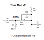
I had one other version of this mod in mind. It behaves the same and is a little cleaner to install. The advantage is you can wire VR3 to the holes in the circuit board that would have been occupied by R8. Use an A50K pot for TONE, remove R8 and wire it like this:

I pulled a schematic for the Octavia 2 from the 'net and redrew it. There are no Build Docs yet for the OctaMayer, but I am 99.9% sure this is how the OctaMayer board is designed just based on the parts. The schematic below shows the Tone Mod. I added VR3 and C22, that's all. Take those off and you have a stock Octavia II. I don't know how Roger Mayer implemented the Tone control in his Vision Octavia. I could not find any schematics for it. If you listen to the demos, the Octavia II and the Vision Octavia sound the same when the Tone control is dimed. I suspect that the circuitry is the same, except the Vision has a Tone control and buffered bypass. On his webpage, Mayer describes the location and purpose of the Tone control as reducing the treble content before the octave stage, similar to rolling back the guitar's tone control. This was a simple way to accomplish that on the OctaMayer board. Be aware that this Tone control does not behave at all like the Tone control on the Foxx Tone Machine and it's not supposed to. It's pretty subtle and works best at low to moderate DRIVE settings. C22 was a guess and I think it could be larger, something like 10nF to 15nF.

With TONE dimed, the freq response is flat from 100Hz on up. With TONE at noon, the response is down 3dB at 600Hz, drops by 11dB at 2KHz and flattens out. With TONE at zero, the response is down 3dB at 600Hz, drops by 20dB at 10KHz and flattens out. Increasing C22 moves those break-points down proportionately. This is true for drive settings below 4:00. When DRIVE is dimed, the TONE control has less effect, which is fine because when we max out DRIVE, we're going for a much nastier tone anyway.
I had one other version of this mod in mind. It behaves the same and is a little cleaner to install. The advantage is you can wire VR3 to the holes in the circuit board that would have been occupied by R8. Use an A50K pot for TONE, remove R8 and wire it like this:


