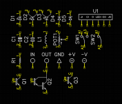
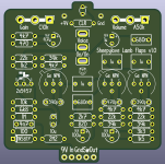
PCB Pins FTW!And one more which was sitting around for weeks now. A dual 3PDT footswitch with 3PDT order switch. Made for 1590BB portrait.
Did you know that 3PDT toggle switches have different pin spacings than 3PDT footswitches? Not that it could be confusing or annoying to find out the hard way..
View attachment 77458
You are using an out of date browser. It may not display this or other websites correctly.
You should upgrade or use an alternative browser.
You should upgrade or use an alternative browser.
Bring out yer Diptrace
- Thread starter Grubb
- Start date
vigilante398
Authorized Vendor
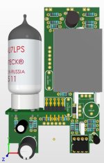
The "what's your favorite reverb build" thread reminded me I never updated this design, so I figured I would pull it up. This is basically a Rub-A-Dub reverb but the TL072 has been replaced by a 12AX7. I know I can put the BTDR2 on the other side of the board and it will fit, but I don't like mounting things against solder pads.

Brett
Well-known member
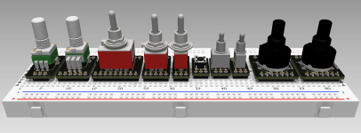
I love Robert's ProtoBoard, but using switches while prototyping has been a bit of a pain. This should hopefully address that. I went ahead and put Alpha RD901 & RD902 pot adapters in there as well since it may be helpful to have them breadboard-mounted in some situations.
Switches include:
3PDT, DPDT, SPDT miniature toggle switches (1M series)
6x6 momentary tactile
DPDT, SPDT sub-miniature toggle switches (2M series)
2P4T and 1P8T rotary switches
Am I missing any "must-have" adapters?
jessenator
Well-known member
I've started something similar. I should just finish the choreBecause I am a psychopath and was annoyed by my schematics not lining up nicely all the time, I went through my component library and standardized all the component sizing:
View attachment 77798
Feral Feline
Well-known member
Big Monk
Well-known member
@Big Monk,
What software is that library being used with?
I continue to use DIYLC for my schematics, even though I've got (and should practice using) Eagle.
I’m a DipTrace man.
I’m sure real PCB designers have moved on to other things like KiCAD and Eagle but DipTrace is what I’ve learned on and it’s what I’m sticking with.
jessenator
Well-known member
Sadly—unless things miraculously changed recently—Eagle's getting rolled up into the Autodesk360Subscriber+ YoullNeverOwnSoftware™ edition platform they've got.
So I think unless folks already had a perpetual license from them, it's going to be a migration to one of the others :/
So I think unless folks already had a perpetual license from them, it's going to be a migration to one of the others :/
finebyfine
Well-known member
I've started something similar. I should just finish the chore
It’s such a game changer. I do hate finding components I haven’t setup to my standard grid (I use 0.1in in schematic editor despite using metric in pcb editor) but it’s sooo nice to get really anal about component text placement without having to change it for each schem.
Here’s my pdf export of a schem for chuck’s chuckaround that I had on my phone and am pretty happy with even though I’ve changed some more spacings since.
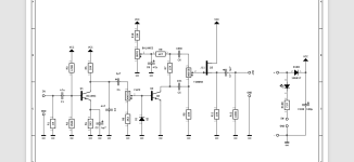
finebyfine
Well-known member
Forgot to label the name / description of this PCB before I had to get going to work, so this show and tell is also a guess the circuit. To make it fair, I added two additional gyrators not present in the original (but inspired by another builder's version of the circuit). Background color may or may not be a hint. Just noticed the 100k silkscreen on the right side of the opamp is facing the wrong way, if anyone else catches others let me know, I hate only catching them when a board's in my hands lmao
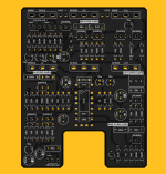

Feral Feline
Well-known member
Boss Hyper Fuzz
2nd guess MZ-2
Wait, only 1 IC, so ... BluesDriver?
2nd guess MZ-2
Wait, only 1 IC, so ... BluesDriver?
finebyfine
Well-known member
Boss Hyper Fuzz
2nd guess MZ-2
Wait, only 1 IC, so ... BluesDriver?
You’re on the right track but this one was only around for one year
Feral Feline
Well-known member
Praise & Worship 2 Boss
PedalBuilder
Well-known member
x
What relay are you using for this? I've been using the FTR-B4CB4.5Z for my relay boards, but it's a through hole device. I'm interested in switching to something surface mounted, and JLCPCB doesn't stock a surface mount version like the FTR-B4GB4.5Z or FTR-B4SB4.5Z.@PedalBuilder really got me interested in his smart IO board so I rigged up my own:
View attachment 77456
Harder to make this work with basic parts from JLCPCB, so the cost is higher than Chuck's basic relay, but the cost is worth the convenience.
Still waiting to verify, but if I did it right (and I often don't) then this should work with 1590B.
PedalBuilder
Well-known member
I'm not sure when this happened, but JLCPCB now has a category of parts called "Preferred Extended Parts" which seem functionally the same as their Basic Parts category in that they are exempt from the $3 Feeder Loading fee that normally applies to extended parts. There used to be about 400 Basic Parts; now there are over 7,300 Basic and Preferred Extended Parts, including a wide range of semiconductors. This should open up a lot more options for SMD projects.
szukalski
Well-known member
The SMD version: https://jlcpcb.com/parts/componentSearch?searchTxt=C126744x
What relay are you using for this? I've been using the FTR-B4CB4.5Z for my relay boards, but it's a through hole device. I'm interested in switching to something surface mounted, and JLCPCB doesn't stock a surface mount version like the FTR-B4GB4.5Z or FTR-B4SB4.5Z.
B3GA4.5Z
B3G and B4G are the same in different dimensions.
I got my layout of your smart IO in and verified. It's a nice little package. I have to play with components to remove extended parts (4x at present), but I'm pretty happy with it. Programming with UPDI is so much easier, just add a RPi, a 1k resistor, and you're set! Even 1590B friendly!
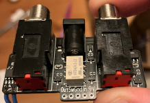
vigilante398
Authorized Vendor
Interestingly enough a little while ago at my day job I was pulled into a design review and the layout had been done in DipTrace. At my old job we used Altium Designer exclusively (and that's what I use for my stuff), at my current job we use Cadence Allegro and OrCAD, but this group had a simple non-production project and got permission to use DipTrace.I’m sure real PCB designers have moved on to other things like KiCAD and Eagle but DipTrace is what I’ve learned on and it’s what I’m sticking with.
KiCAD and Eagle are popular with hobbyists, including serious hobbyists, but I've never seen them used in a professional setting.
PedalBuilder
Well-known member
It looks great! And from your description it sounds like it runs fine without the 100µF cap from 5v to ground, which makes me feel better about omitting it from future iterations.I got my layout of your smart IO in and verified. It's a nice little package. I have to play with components to remove extended parts (4x at present), but I'm pretty happy with it. Programming with UPDI is so much easier, just add a RPi, a 1k resistor, and you're set! Even 1590B friendly!
View attachment 78060
Similar threads
- Replies
- 0
- Views
- 178


