King Nothing Low Volume

bluedmc777

Active member
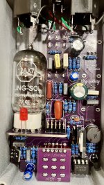
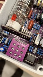
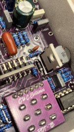
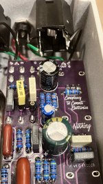
Is it normal to have to crank the volume and gain almost to all the way up when in middle gain and low gain modes. I figured it was normal, though strange, to have to crank these until a friend tried it and said it didn’t sound right at all. He’s owned a sushiboxfx v1 bought directly and also has a Harlot. What could be causing such low gain? A bad Jfet possibly? I have a new Tung-Sol that I know is good. Any suggestions?

Running the pedal 9v 500ma on a 1Spot CS7 Pro and have also tried it on a 500v Boss adapter.
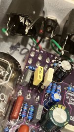
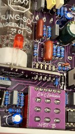
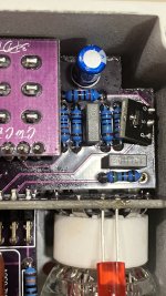
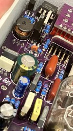
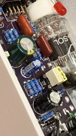
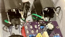
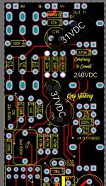
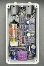
 

Attachments

  • IMG_5731.jpeg
    IMG_5731.jpeg
    710.9 KB · Views: 27
Last edited:
@vigilante398 Is this normal brother? Having to crank the volume and gain almost all the way up on center position? Switching to far right everything needs to be turned all the way up. This is regardless of mode high pass switch.
 
@vigilante398 Is this normal brother? Having to crank the volume and gain almost all the way up on center position? Switching to far right everything needs to be turned all the way up. This is regardless of mode high pass switch.
Nope, that's definitely not normal. If you're using a known-good tube and a known-good power supply (either of those listed should be fine) then you need to start looking at the circuit; the JFET would certainly be a good suspect. While you're in there also be on the lookout for things like solder bridges and wrong component values.

So is this only on some switch settings and not on others? I'm not clear on that point.
 
It’s on all switches it just becomes more apparent in mid and right position which seems I assume is mid gain and lowest gain because there is more gain and output in the left position. Assuming each switch drops the gain a little from left to right.

The tube was a new tube was working fine however it did sit in the box for a couple months before I installed it into the Pedal. Maybe I damaged it putting it into the socket.

I have the particle accelerator as well, and it has a lot more volume there’s no way I could dime it. Could an intermittent power jack cause volume loss. It’s one of the damn thinline jacks which always seem to be problematic eventually
 
@vigilante398 @Tassieviking There lies the problem…I sold the pedal to a guy that used to own a king nothing and he immediately called and said something wasn’t right.

I’m gonna meet and give him his money back this weekend and I’ll take a look and post some close ups. I appreciate you guys tuning in. Is it possible for one of those cheap thin inline power inputs to cause something like this? There has been a time or two it’s was intermittent from the jack. After thinking about it I’ve had ALOT of problems with those jacks. I don’t know when diy switched to those jacks.
 
I’ll be getting the pedal back tomorrow and will post some close-ups. Thanks to everyone that has helped. Very much appreciated!
 
Hopefully these will help.
 

Attachments

  • IMG_5301.jpeg
    IMG_5301.jpeg
    542.2 KB · Views: 21
  • IMG_5302.jpeg
    IMG_5302.jpeg
    479.1 KB · Views: 21
  • IMG_5303.jpeg
    IMG_5303.jpeg
    474 KB · Views: 22
  • IMG_5304.jpeg
    IMG_5304.jpeg
    425.6 KB · Views: 22
  • IMG_5305.jpeg
    IMG_5305.jpeg
    409.6 KB · Views: 22
  • IMG_5306.jpeg
    IMG_5306.jpeg
    472.4 KB · Views: 22
  • IMG_5307.jpeg
    IMG_5307.jpeg
    410 KB · Views: 22
  • IMG_5308.jpeg
    IMG_5308.jpeg
    405.6 KB · Views: 20
  • IMG_5309.jpeg
    IMG_5309.jpeg
    417 KB · Views: 19
  • IMG_5310.jpeg
    IMG_5310.jpeg
    406.1 KB · Views: 21
Can you get some pics of the other side of the board? If there is a solder bridge somewhere that is where it will likely be. You may also want to reflow the Drain on your jfet. It looks a little suspect based on the picture. Also double check the 2 caps you have in sockets to make sure they are in there good. If they wiggle at all it can cause problems. Ask me how I know, lol.
 
None of the pot support tabs are soldered. I think the build docs state to solder for ground. I have no idea if this is the issue or not, but figured I would point it out
 
None of the pot support tabs are soldered. I think the build docs state to solder for ground. I have no idea if this is the issue or not, but figured I would point it out
It's a good idea to solder them in, but not soldering them won't prevent proper operation. It's more for stability than for continuity as the pads for the support tabs are snug enough that you get an interference fit just with them pressed in.
 
I switched the caps back to the original values. While it did change the frequency or low end there wasn’t a change in volume. Below are my unity gain settings for first and second mode. Or distortion>less distortion-boost? I didn’t bother taking a pic of the Last mode as it couldn’t reach unity volume.

This guitar pedal to amp only. I’m using a new D’Addario 9v 500ma power supply here. Volume and master both at about 11 o’clock on a bad cat cub 40r. It’s pretty loud. Center bass response each time only.

IMG_5402.jpeg IMG_5403.jpeg
 
Anyone mind sharing if those control levels are right? Again 1st pic is higher gain “far left”, 2nd js medium gain center position, and the lowest gain really couldn’t reach unity. Bass mode was left in center position the whole time. Also, I did swap back to the original caps.
 
Hello bluedmc777,
From what I remember unity is gain at 9 o'clock and level at 1 o'clock when the mode is on the right side.
I will do some measurement to confirm it.
Do you have a multimeter? To do some measurement on your King nothing.
 
Hello bluedmc777,
From what I remember unity is gain at 9 o'clock and level at 1 o'clock when the mode is on the right side.
I will do some measurement to confirm it.
Do you have a multimeter? To do some measurement on your King nothing.
Thanks for the info. Yea mine is definitely off then if that’s unity on the mode to the right. I’m currently on vacation so it’s been placed on hold for the time being. However I do have a multimeter and would be interested in your readings only if you have the spare time. Appreciate your help.
 
Did you figure this one out ?
Is the mode switch the correct ON-ON-ON switch or could an ON-OFF-ON switch have gone in by mistake ?
Works been busy and I haven’t had a chance to take it apart yet. I’m still pretty new with all this. That’s a good question though. What would be the outcome of using on-off-on? I know mode 1 left has the most output and center position is less and mode 3 can’t really reach unity gain. I’m on vacation at the moment or I’d pop it open and see. Does seem that’d be an easy thing to overlook.
 
Thanks for the info. Yea mine is definitely off then if that’s unity on the mode to the right. I’m currently on vacation so it’s been placed on hold for the time being. However I do have a multimeter and would be interested in your readings only if you have the spare time. Appreciate your help.
At first you can check the power supply.

This is what I had in mine : 240V lower pin of R1, 37V for the transistor at lower pin of R3 and 31V at the higher pin.

Attached the measurements points.

I will ready for you an other set of measurements to help you, this time it will be signal so a signal generator will be use, it is easy to have a free signal generator if you don't have one (pc, smartphone...) let me know if you need some help.
 

Attachments

  • Screenshot_20240731_164158.jpg
    Screenshot_20240731_164158.jpg
    601.6 KB · Views: 4
Works been busy and I haven’t had a chance to take it apart yet. I’m still pretty new with all this. That’s a good question though. What would be the outcome of using on-off-on? I know mode 1 left has the most output and center position is less and mode 3 can’t really reach unity gain. I’m on vacation at the moment or I’d pop it open and see. Does seem that’d be an easy thing to overlook.
I don't know what would happen if the wrong type of switch was used, I only thought of it when I ordered a King Nothing PCB yesterday and I started to check if I had to order any parts for my build.
I just seemed like that was the area you were having problems so I thought I should mention it, I had a good look at your pics above and all resistors seem to be correct from what I can see so one has to start checking everything else in the circuit.
Perhaps Nathan would know what happens if the wrong switch is used.
Cheers
Mick
 
Did you figure this one out ?
Is the mode switch the correct ON-ON-ON switch or could an ON-OFF-ON switch have gone in by mistake ?
I just got the kit. It says on on on for dpdt, but I got on off on. Trying to read the schematic and figure out what works and not, but I couldn't figure it out.
My understanding is that On on on Dpdt have two versions on what connects in the middle position. Since type 1 or 2 is important for on on on and there is no mention of the type, I can only guess that on off on also works?
Feel free to expand @vigilante398
Thanks

Screenshot_20240801_004733_Chrome.jpg
 
Back
Top