Chaos Machine circuit noise

proffbass

New member
Hi,

I tried out my new build and got a car alarm high pitched oscillating sound from it.

Here is a clip I put on Youtube so you can hear it. This clip is with the input cable removed from the pedal.


I pulled out the input cable and the sound continued.

I tested my circuit before putting it in the enclosure and didn't hear anything wrong but I hadn't connected two of the pots or the LED. Or input connections, expression pedal inputs etc.

Can you please advise me how to go about diagnosing the issue?

Let me know what sort of pictures to supply if that would help.

Thanks.
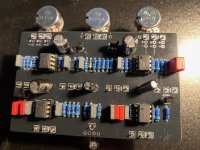
Choas PCB.jpg
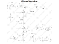
Chaos Schematic Screenshot.png
 
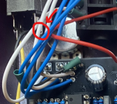
Pictures of the soldered side would be helpful (though of course kind of difficult to see everything with the pots in the way).

Pot in bottom right of picture looks suspiciously soldered. (Middle pin may not be making contact). Dunno if that'd cause
those specific issues or not. Really all of the pots look like they could use some more solder.

Where'd you get your TL072's, do you have any others from a different source? Sometimes those are counterfeited
but if you got them from Mouser/Digikey you have no need to worry.

Do you have an audio probe? They are tremendously helpful in situations like these, to find the place where the oscillation
starts can really narrow down the search space.
 
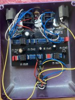
IMG_7491.jpeg
Here is the current look of the component side of the PCB.
I will try the audio probe to identify the source of the issue.
As suggested, the solder side is heavily masked by pots.
Thanks for your suggestions.
I really value the input.
This was my first component purchase build. So I bought the components from Tayda rather than getting them supplied with a kit.
I’ve learned a lot since placing the order. I ordered some solder lug input jacks for the expression pedal inputs but they didn’t fit in the space I had left myself with the artwork for the holes.
 
Pictures of the soldered side would be helpful (though of course kind of difficult to see everything with the pots in the way).

Pot in bottom right of picture looks suspiciously soldered. (Middle pin may not be making contact). Dunno if that'd cause
those specific issues or not. Really all of the pots look like they could use some more solder.

Where'd you get your TL072's, do you have any others from a different source? Sometimes those are counterfeited
but if you got them from Mouser/Digikey you have no need to worry.

Do you have an audio probe? They are tremendously helpful in situations like these, to find the place where the oscillation
starts can really narrow down the search space.
thanks for your input into my pedal issues.

I appreciate all the feedback I can get.

I tried replacing the ICs but this did not stop the buzzing or clicking which becomes a buzz as the rate is increased. i also recorded the voltage of all the legs of the ICs some were oscillating so i have recorded the voltage range.

I used my audio probe to test the signal path and eventually all the components to try to get a better understanding of the issue.

I can see a pattern emerge but it doesn't help me figure out which component is at fault to replace or how to reconfigure the circuit to produce less noise.

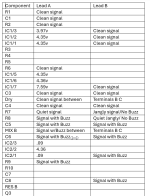
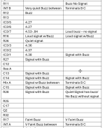
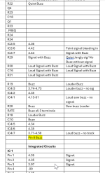
in the results i have tried to record whether there is a signal traceable and if there is a buzz in the component without a signal being put through the pedal. it is easier to record the components which either have only a buzz present and no signal or those which do not have a buzz after the signal is stopped.

I tried to follow the signal path logically in the table below but had to make choices as there are many parallel paths within the schematic.

I am getting better at interpreting schematic diagrams but am still new to the process.

Here is a link to the noise I have been experiencing with the pedal.

Here is a table of results from my testing with an audio probe.

 
If you tested the pedal and it was fine before installing the last two pots, LED, and exp jacks, then I would start by desoldering those components wire by wire until you find the component that stops the noise. Then inspect that and replace it if necessary
 
Good thorough notes! I think there's something wrong at IC2/3. That pin is tied right to VREF_A and other things that are tied to VREF_A seem to be okay, but that one is ~zero volts - so either it's floating unconnected or it's near-shorted to ground. Check your socket there there there aren't solder bridges around there. It should have continuity to IC3/3 (Or anything else labeled VREF_A on the board) but I suspect it has continuity to ground somewhere (or is unconnected - maybe more likely given the fact that VREF_A is okay in other places) It's also possible that there's something going on with pin1 of that IC but I think pin 3 is more likely.
My limited, paint-by-numbers understanding of op-amps is that they're going to try to keep the two input voltages the same by changing the value of the output (which is then linked to one of the inputs via a feedback network). In this case, the value of one of the inputs is ~ground, so it's pulling the output to ground in an attempt to get it to match. (IC1/7 being >7V is also suspicious but it's also tied to the other input of IC2/3)
Thank you so much for your input.

I will definitely follow up tomorrow and let you know what I find out based on your notes.

Thanks again.

It is very much appreciated.
 
Thank you so much for your input.

I will definitely follow up tomorrow and let you know what I find out based on your notes.

Thanks again.

It is very much appreciated.
Good thorough notes! I think there's something wrong at IC2/3. That pin is tied right to VREF_A and other things that are tied to VREF_A seem to be okay, but that one is ~zero volts - so either it's floating unconnected or it's near-shorted to ground. Check your socket there there there aren't solder bridges around there. It should have continuity to IC3/3 (Or anything else labeled VREF_A on the board) but I suspect it has continuity to ground somewhere (or is unconnected - maybe more likely given the fact that VREF_A is okay in other places) It's also possible that there's something going on with pin1 of that IC but I think pin 3 is more likely.
My limited, paint-by-numbers understanding of op-amps is that they're going to try to keep the two input voltages the same by changing the value of the output (which is then linked to one of the inputs via a feedback network). In this case, the value of one of the inputs is ~ground, so it's pulling the output to ground in an attempt to get it to match. (IC1/7 being >7V is also suspicious but it's also tied to the other input of IC2/3)
No luck, my friend.

Thanks again for your suggestions but, there is no short circuit to ground and IC3/3 has a strong connection to Vref_A.

Do you think there is anything to the buzz my audio probe picked up on IC4/8? It doesn't seem to be part of the signal path on the schematic.

Anyway...

The IC pins tested as

IC1/4 Ground
IC1/5 Vref A

IC2/3 Vref A
IC2/4 Ground
IC2/5 Vref A

IC3/3 Vref A
IC3/4 Ground

IC4/4 Ground

Thanks again.

I really appreciate your help.
 
Do you think there is anything to the buzz my audio probe picked up on IC4/8? It doesn't seem to be part of the signal path on the schematic.

It's possible that's an issue - are the other pin 8's also noisy? (There's a small resistor between which might help the noise though).
IC4 is part of the LFO (low frequency oscillator) so it's not super unusual for stuff in there to make weird noises but it is odd for the VCC pin itself to be noisy. Maybe there's something going on in the LFO section with all of those expression pedal input thingies -- I'm not sure what kind of frequency the LFO should oscillate at. Does the buzzing change when you change the rate control?

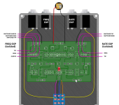
If you short all of the expression pedal things, does it work better? (e.g. the "Alternate wiring diagram" with no expression inputs?). I don't think you need to de-solder anything, you can just temporarily bridge them with wire.

The really low voltage around IC2/1 is still suspicious, does pin 1 have continuity to ground somehow? (And if not continuity, what does the resistance measure between IC2/1 and GND?)
 
Back
Top