
You are using an out of date browser. It may not display this or other websites correctly.
You should upgrade or use an alternative browser.
You should upgrade or use an alternative browser.
Mantle Fuzz (MXR Blue Box) voltages
- Thread starter GiveUsYourBones!
- Start date
Nostradoomus
Well-known member
Nice one! Mine worked out the gate but this is a slick idea
GiveUsYourBones!
New member
Thanks, yeah mine worked great until I fudged the octave mod and shorted pins 1 and 3 on the CD4013.... Luckily I was building 2 at the time so I took the voltages from the working one.
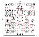
Hi guys, The Mantle Fuzz was my second pedal build and I'm having a couple issues and need some guidance. It is woking but it doesn't seem to be loud enough, and the actual effect seems odd (wish I could describe it better). Anyway, i've checked all the components to ensure they're the correct values and have checked for any simple mistakes (wiring incorrectly, solder bridges, etc...) and everything seems fine.
1. I checked all components and my 56K resistors are mostly registering around 32K on my multimeter. is that an issue?
2. I have checked the voltages and have my calculated numbers in the photo. the majority seem to be spot on, or very close. several seem to be way off from the ones GiveUsYourBones has listed. I am not sure why they are so far off and how to correct the issue?
Thank you in advance!
Attachments
Chas Grant
Well-known member
Which 56K resistors are you referencing as 32K. There are a lot of 56K resistors in this circuit. If taking resistance measurements in a circuit, there may be parallel paths that are not readily apparent, this will cause the resistors to read lower than their marked value. So the readings you are getting may be normal. You have to look at the schematic to see if you have a parallel path and take that into account.Hi guys, The Mantle Fuzz was my second pedal build and I'm having a couple issues and need some guidance. It is woking but it doesn't seem to be loud enough, and the actual effect seems odd (wish I could describe it better). Anyway, i've checked all the components to ensure they're the correct values and have checked for any simple mistakes (wiring incorrectly, solder bridges, etc...) and everything seems fine.
1. I checked all components and my 56K resistors are mostly registering around 32K on my multimeter. is that an issue?
2. I have checked the voltages and have my calculated numbers in the photo. the majority seem to be spot on, or very close. several seem to be way off from the ones GiveUsYourBones has listed. I am not sure why they are so far off and how to correct the issue?
Thank you in advance!
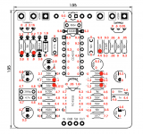
Thanks. I am not experienced enough to reliably follow a schematic to check for parallel paths, but I will give it a shot. I have used a red dot to indicate the resistors that are registering around 32k on this screenshot. That would make sense the reason why some are registering a different value. I checked each component with my multi before installing on the board and everything registered correctly.
Any thoughts on the differing voltage readings? specifically the pins on CD4013 seem to be vastly different.
Any thoughts on the differing voltage readings? specifically the pins on CD4013 seem to be vastly different.
Attachments
BuddytheReow
Breadboard Baker
If you tested all components before soldering and still notice resistance after, regardless of the value, you should be alright. Did you check caps too?
Chas Grant
Well-known member
The CD4013 is a Flip Flop, the voltages on this will seem weird until you look at them and the schematic and the pin out of the chip. Pins 4, 6, 8, and 10 are grounded and should be 0V, which they are. 12 is connected to 9, they should be the same, they are. 2 is connected to 5, they should be the same, they are. 13 is connected to 3, they should be the same, they are. Pin 14 is Vcc, good and pin 7 is ground also good. The Flip Flop will change states when CL2 (Pin 11) goes from low to high, this will depend on the signal from the guitar. The strange voltage I see is on the transistor on the top right. You have .05, it should be higher. Look at the other transistors.Thanks. I am not experienced enough to reliably follow a schematic to check for parallel paths, but I will give it a shot. I have used a red dot to indicate the resistors that are registering around 32k on this screenshot. That would make sense the reason why some are registering a different value. I checked each component with my multi before installing on the board and everything registered correctly.
Any thoughts on the differing voltage readings? specifically the pins on CD4013 seem to be vastly different.
As for the 56K resistors, I don't see the circuit designations any where, just the component values. But you have 8 of them with red dots, and looking at the circuit there are 8 that have parallel paths.
Chas Grant
Well-known member
OK, the transistor in question looks like Q1. The 0.05 should be reading the same as pin 11 of the CD4013, its not. Check resistance between the pin 3 of the transistor and pin 11 of the CD4013

Dan0h
Well-known member
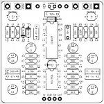
This is such a great idea having an image of the PCB with all the V values. Would save a ton of time trouble shooting and forum diving, but would also take a lot of work to put together.In case anyone needs them, here are the voltages from a working mantle fuzz pcb.
Chas Grant
Well-known member
OK check resistance between these points, should be close to 0 ohms. Electrically they are the same point so they should have same voltage. When the transistor conducts, the voltage goes low but should be greater than .6V, when the transistor is not conducting it will go high up to +9V.just checked and im registering 0 resistance between pin 11 on CD4013 and pin 3 on the transistor.

Chas Grant
Well-known member
And you are sure that you have 4.5 on pin 11 and .05 on the 3 other points (scratching my head)
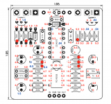
Okay, so two things. 1. I have no idea why it is different now (I'm sure I did something wrong just not sure what), but i'm reading 44.4mV (0.04V) on all the points listed above. 2. my power supply is now supplying 7.9V instead of 9.3V as I recorded earlier. I checked the voltage on all points, and a couple of the values are now quite different (as seen in blue on this graph). most are the same or within a reasonable margin.
I truly appreciate your help with this.
I truly appreciate your help with this.
Chas Grant
Well-known member
Now we might be getting somewhere, those values make more sense. Either you have a short to ground or the 10K resister is opened, my guess is on the short to ground. Take a resistance reading from the same points to ground, the first one will tell you if you have a ground. The resistance should be fairly high if good. If its low, first carefully remove the CA4013 and recheck. If resistance is still low after removing CA4013, try replacing the transistor, that's the most likely culprit. If resistance is high after removing CA4013, then replace the IC.
If on your initial check, resistance to ground is high then measure 10K resistor below the transistor on the right. An open resistor would give you the same voltage readings.
And its no problem helping you out. I learn a thing or 2 doing this and that's always good.
If on your initial check, resistance to ground is high then measure 10K resistor below the transistor on the right. An open resistor would give you the same voltage readings.
And its no problem helping you out. I learn a thing or 2 doing this and that's always good.
Similar threads
- Replies
- 11
- Views
- 526
- Replies
- 17
- Views
- 391
- Replies
- 12
- Views
- 696
- Replies
- 1
- Views
- 299