
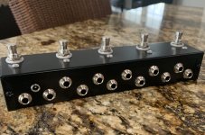
So I’ve built a true bypass switcher with one tuner loop and four loops. I bought four common anode bicolor leds for the four loops. I want to wire the led to the 3PDT so that the led is red when bypassed and green when engaged versus the one on or both on setup. I could hook one side up to the normal led spot on the footswitch (lug 2) with ground in the middle on lug 5 which would make it green when engaged. My question is instead of wiring the red right to ground so it’s always on, could I wire it to lug 8 (lug 8 is jumped to lug 1) so that it’s connected to ground when the loop is bypassed? My only concern is that when the loop is engaged, it’s not connected to ground but it’s still jumped to lug 1 which is the loop send. Would that cause any issues? Would the loop send be connected through the led to ground or the cathode?
You are using an out of date browser. It may not display this or other websites correctly.
You should upgrade or use an alternative browser.
You should upgrade or use an alternative browser.
Question on how to wire a common anode LED
- Thread starter ADAOCE
- Start date
knucklehead
Active member
What a great gadget - to you have a schematic for this?
..:: How to make your own True Bypass Strip ::.. taken from www.singlecoil.com
singlecoil.com - the musicians DIY electronics source for free
www.singlecoil.com
I basically followed the project on this page. There is a ton of info in here about other things you can do like master bypass, wet and dry split, tuner mutes etc. I opted for the tuner and four loops. It’s really simple it’s just wiring five true bypass 3PDT switches in a row. There are schematics on the page though to help you visualize it.
knucklehead
Active member
I basically followed the project on this page.
Thx!
Wish I saw that a couple weeks ago but thanks for pointing it out.The 3pdt boards at guitarpcb, would likely be the easiest way, there already set up for common anode and have the CLR on them
I’m wiring up the switches in this scheme
Is there no way to do this way? The real problem is the red green bicolor is not very good. The green is pretty dim compared to the red. Im trying to see if I have the green always on and switch the red side off when engaged just not sure where to put it
Attachments

Mcknib
Well-known member
Just wire ground for the bypass colour to lug 6 that's grounded in bypass mode by lug 5 the same as 4 is grounded by 5 in effects mode remember the middle row is common to the top and bottom row or throw so when it's switched or thrown to bypass 5 grounds 6
Lug 1 is jumpered to 6 which I think you're referring to as 8 so yes connect your red side cathode to there

Lug 1 is jumpered to 6 which I think you're referring to as 8 so yes connect your red side cathode to there
Last edited:
Is this numbering correct? It sounds like you’re describing the transpose of what I think the numbering is.Just wire ground for the bypass colour to lug 6 that's grounded in bypass mode by lug 5 the same as 4 is grounded by 5 in effects mode remember the middle row is common to the top and bottom row or throw so when it's switched or thrown to bypass 5 grounds 6
Lug 1 is jumpered to 6 which I think you're referring to as 8 so yes connect your red side cathode to there
Attachments
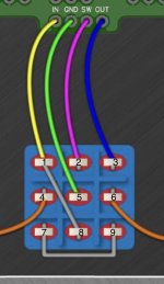
Right that totally makes sense idk why I was thinking it would be numbered across. To be fair I added the numbers to the second image!I should look at images! we're talking about the same lug your 8 is my 6
The columns are the poles as you know a 3PDT is basically three SPDTs side by side so I've always counted the pole lugs the standard way top to bottom
But we're talking about the same lug
sweet I’ll get this thing wired up. Kind of tedious all this wiring though I would easily pay for a loop master box they seem to be priced well
Mcknib
Well-known member
To be honest I never even looked at the image, story of my life jump right in
Me building a wardrobe:
Instructions? What instructions, oh I musta binned them! Hold on and I'll put this door the right way up
Meant to say you will find the green side dimmer you can get round it by having separate CLRs on the cathodes instead of the anode higher value red side and minimum green side would even them up a wee bit
Last edited:
Hah I hear you on that. I get that sense of confidence and then realize I put some part backwards...To be honest I never even looked at the image, story of my life jump right in
Me building a wardrobe:
Instructions? What instructions, oh I musta binned them! Hold on and I'll put this door the right way up
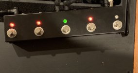
@Mcknib so I finished wiring this thing up and all the wiring checks out I get bypass when I should and shouldn’t but the four loops that have the red side on lug 6 make a huge pop sound when you engage the loop. It also distorts a little bit when you play. Bypass functionality is perfect. I’m thinking the led being connected to the loop is causing this reaction which is what I was afraid of. Maybe I can put a resistor or something somewhere?
the red green on off function looks cool but at the end of the day I need function over form
the red green on off function looks cool but at the end of the day I need function over form
Attachments
Mcknib
Well-known member
There's some info regarding LED pop here
 www.muzique.com
With the red side being brighter it could be the sudden switch in current requirements that's causing it
AMZ - LED Popping
How to stop the pops in audio from LED current surges when switched.
With the red side being brighter it could be the sudden switch in current requirements that's causing it
Last edited:
Many__Of__Horror
Active member
I've had about 50/50 luck with popping when using these LEDs in builds. Never had a pop from a standard LED@Mcknib so I finished wiring this thing up and all the wiring checks out I get bypass when I should and shouldn’t but the four loops that have the red side on lug 6 make a huge pop sound when you engage the loop. It also distorts a little bit when you play. Bypass functionality is perfect. I’m thinking the led being connected to the loop is causing this reaction which is what I was afraid of. Maybe I can put a resistor or something somewhere?
the red green on off function looks cool but at the end of the day I need function over form
Mcknib
Well-known member
Yeah I'm not a massive fan of them don't see the point unless you're gigging in dark venues then it's a visual showing you've not forgotten to power itI've had about 50/50 luck with popping when using these LEDs in builds. Never had a pop from a standard LED
Tha is for the info yeah I’m thinking that’s the likely culprit because the first loop is just a standard led and no pop. Might just clip the red side so it’s green onlyThere's some info regarding LED pop here
AMZ - LED Popping
How to stop the pops in audio from LED current surges when switched.
With the red side being brighter it could be the sudden switch in current requirements that's causing it
Glad I’m not alone in this! It’s too bad because it looks neat but oh well I’ll eventually replace the switches for relay bypass and soft clicks at some pointI've had about 50/50 luck with popping when using these LEDs in builds. Never had a pop from a standard LED
knucklehead
Active member
I am likely to build something similar - a summing buss for 4 pedals with a master bypass - and intend to use Tayda's red/green self-indicating switches. Your post inspired this.
THAT said . . . .
Is your DC power source isolated from the enclosure or do they share your box's ground?
THAT said . . . .
Is your DC power source isolated from the enclosure or do they share your box's ground?
Similar threads
- Replies
- 6
- Views
- 523
- Replies
- 7
- Views
- 321