Sunflower Fuzz Help

Rcmatz

Member
This is my second pedal build. Thanks for any advice in advance.

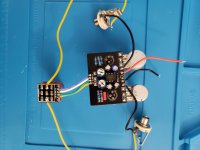
I am troubleshooting outside of the enclosure

I removed the 2n404 transistors for the photos. I added a bunch of SIP so that I could test different components in the circuit.

When it is not plugged in, and the footswitch is disengaged I can get sound.
When it is plugged in, I can not get sound
If it is not plugged in, and the footswitch is disengaged and I am hearing sound, once I connect only the ground from the DC jack, the sound cuts off.
I have been able to measure voltage across most of the board, I haven't gone pin by pin yet
If I connect +/- as the board calls for, the LED does not light up.
If I inverse the +/- the LED will light up

I can get voltage readings at C3. I can not get any voltage readings at the volume knob. I have re soldered the volume knob.
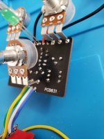
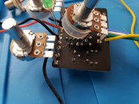
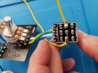
20210729_212842-min.jpg 20210729_212849-min.jpg 20210729_212855-min.jpg 20210729_212533-min.jpg
 
I'm so new to this (software guy with a soldering iron), more than half of what I am doing is fumbling around. I am unsure what you mean. Would you mind explaining what I missed? I am guessing you are asking why I soldered to the lugs on the 3pdt stomp instead of the two open spots on the little breakout? I wasn't sure they served that purpose. In the build doc it showed soldering to the lugs so I just followed the image. I was saving testing those out for when I wasn't troubleshooting.

Also, if you are coda from the coda-effects webpage, I really appreciate your sunface circuit analysis and troubleshooting pages! The page on the sunface is why I decided to try this out with all the swapable options to play around.

One step closer, I definitely had the LED reversed, I still get no voltage at the volume pot, and I still get no sound when powered. I was able to test R4 was getting voltage before I slipped and shorted the LED. Gonna have to start there tomorrow.

Thanks again for looking
That’s exactly what I was referring too. What you did should work fine, I just wanted to make sure that there wasn’t anything wrong with the breakout board. Troubleshooting is all about the process of elimination, after all…

Alas, I am not Coda-Effects…just someone too lazy to come up with a new username so I use the one I used on a Led Zeppelin forum 20 or so years ago…
 
Thank you for the advice. I really appreciate it.

I am getting closer. I went pin by pin checking voltages and it turned out that I had voltage on one side of C3 but not the other. Once I reflowed that I was able to get closer.

With the pedal plugged in, but off, I can now get sound (I couldn't before). Once I turn it on, I immediately lose sound, at all POT settings I had time to try in my short window.

Question for experts
1) why, with that C3 CAP not previously soldered correctly, would I lose sound with the pedal turned off when I only applied ground

My next ideas to chase are are
1) My transistors are sitting in the SIP precariously, and I am wondering if I don't have a connection issue there. Also, the board doesn't label BCE, I am aligning the Tabs, but it seems not all Transistors have the same pattern and I am wondering if I don't have a wrong-pin in the wrong slot problem.
2) Taking measurements at the output audio jack to determine if I am losing something between the volume pot and the output
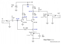
3) I am planning to check voltages to compare to the following and see if I can uncover something. https://www.electrosmash.com/fuzz-face
 
The pinouts match up, so you are good there. How about the trimpots? Have you adjusted them at all? Can you read any voltages at the transistors?…
 
I have adjusted the trim pots
Clean Trim: all voltages read 0 (I assume because no guitar input signal???)
C1 which connects to the clean trimpot reads -.1 on the negative terminal and 0 on the positive
Bias Trim: Left -7.63 top 0 right -8.0

Transistors I believe the Emitter is next to the tab and the base is in the middle, if so:
Q1 Transistor E:0 B: -.1 C: -.34
Q2 Transistor E:-.25 B: -.34 C-5.64

IC by pin:
1: 9.48
2: 5.6
3: 0
4:-3.7
5: 9.48
6: 4
7: 4.7
8:-9.26
 
Curious point that I don't know what it means.

When the 3pdt is off, the LED is on but dim: The Cathode measures 6.75v and the Anode measures 8.4
When the 3pdt is on, the LED is on but bright The Cathode measures 6.63v and the Anode measures 8.4
 
First thing to do is make sure you have your in cable going to your in jack and out cable to out jack it's very easy to mix them up with it not being in an enclosure your in jack is on the left and not the right as it would be in it's enclosure you'd get bypass signal but no effect

Your transistor voltages don't look too far off it should pass signal

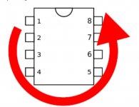
IC1 voltages are ok albeit you've got the right hand pin numbers mis labelled but you've got inverted voltage where you want it pin 5 (your 8)

Pin numbering like this

20201124_153036.jpg

If you're not familiar with using an audio probe I'd suggest with it being a small circuit reflowing all your solder joints just hold your iron on the joints for around 4 seconds until you get a nice flow making sure you get a good solder joint between solder pad and component legs/ pins I'd reflow the solder joints on your in and out jacks too it doesn't look as if the solders melted very well on the one's I can see

Remove your transistors from their sockets before you reflow the socket solder joints and looking at your voltages you don't need to reflow IC1

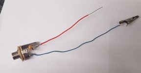
With an audio probe you can trace the signal from in to out to see where you lose it, it's not too difficult and the probe itself is easy to make and use

All you need to make a quick probe is a mono jack, a 100n to 1u film or ceramic capacitor, 2 bits of wire and a clip

20200420_174549.jpg
 
Last edited:
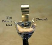
Hey, if you're still having trouble with this, it looks to me like you have the hot (lead) and ground wires backwards on your input and output jacks. The two black wires coming from the top of your board should go to the inside lug on your jack - the Ground in the picture below. The yellow wires should go to the hot lug - the (Tip) Primary Lead in the photo below. It's a little hard to see in your photo but I think those are backwards. That would definitely cause your signal to cut when introducing power since it would ground the tip of your jack.

Switch wiring.jpeg
 
Hey, if you're still having trouble with this, it looks to me like you have the hot (lead) and ground wires backwards on your input and output jacks. The two black wires coming from the top of your board should go to the inside lug on your jack - the Ground in the picture below. The yellow wires should go to the hot lug - the (Tip) Primary Lead in the photo below. It's a little hard to see in your photo but I think those are backwards. That would definitely cause your signal to cut when introducing power since it would ground the tip of your jack.

View attachment 14465
Sorry didn't see this before I posted
 
Thank you both! I think I reworked (damaged) the board enough that I decided to take a step back and work on a sandspur. I am reusing the stomp from the sandspur which came along with the Jacks and the mis wired jacks was definitely one of my problems which is fixed now. I am also struggling on the sandspur, so I will ask my newbie questions on that one here as well.

1) I ordered BC183. I believe I learned how to use my mulitimeter to validate the B-C-E which, with the flat face towards me, my measurements say they are E-C-B. I insulated one of the legs, and bent them to align with E-B-C which I believe is the sandspur layout - Is that correct?

2) I have no audio, and am back to needing to build the tester suggested above. I have traced voltage all the way through. I get to C3, on the outside leg I have a reading of 8.4V and on the inside leg reading I get .1mV. At the Volume pot, I measure .1 mV. I replaced C3 and tested it prior to putting it into the circuit. I tested the C3 I removed, both were near the 10nF. I have reflowed all of the volume pot pins.


Also, just a tip for anyone who is new like me, when I searched the forum for sandspur, there were some good photos of the guts as someone else has successfully built it. That alone has helped me troubleshoot a few gotchas.

Randy
 
I think I may have localized my problem, but I don't know what to do with it. I have copied the image from https://www.electrosmash.com/fuzz-face

I am using NPN so I believe all my readings should be positive not negative.

I think one-of my issues may be the point between C1, Q1 Base and R4. They all measure ~500mv.

On the other end of R4 and at Pot1 I measure .6V
On the other end of C1 I measure .63V
On the Collector for Q1 I measure 1.255V
On the Emitter for Q1 I measure .1mv

I have replaced C1
I have reflown R4 and Q1, though Q1 is messy due to me replacing transistors as a result of the wrong orientation mentioned above. I'm essentially surface mounted with a full hole of solder.


1628115282078.png
 
What's going on? Are you building an NPN Fuzz Face or a PNP?

You can't just mix and match the two.

If NPN then you don't need the voltage inverter chip, and your electrolytic caps will need to be oriented correctly ie NEGATIVE TO GND, the opposite of the ElectroSmash schematic you've posted.


Ahh okay, I see you've switched from a Sunflower to a Sandspur...
... I decided to take a step back and work on a sandspur. ... I am also struggling on the sandspur, so I will ask my newbie questions on that one here as well.

...Randy
No, don't, not "here as well."

Please start a separate thread for the Sandspur problems... That will make it easier for all concerned.
 
Back
Top