You are using an out of date browser. It may not display this or other websites correctly.
You should upgrade or use an alternative browser.
You should upgrade or use an alternative browser.
Fun with JFETs and servos
- Thread starter jubal81
- Start date
Chuck D. Bones
Circuit Wizard
Chuck's thread on the Brownout OD finally motivated me to do some breadboarding with JEFTs and opamp servos for biasing.
So far, things are looking pretty neat. I put together a couple stages of the Wampler Black 65 for testing and sure enough, I'm able to swap in and out JFETs willy-nilly and have it bias up perfectly. I don't have any J201s, so I've been using 2SK170, 2Sk117 and the good old 2N5457. I've got it set up so I'm getting 5.8V on the drains with a 9V supply. When they begin to break up, the distortion looks identical on the scope, the only difference being that the higher |vp| transistors have less gain/more headroom.
As far as the Black 65 goes, I've read that they're set up with 4V on the drains and I've not been able to dial it that low with this setup and my JFETs. (Using a rail-rail JFET opamp). I've always done 5.8 or so on a 9V supply with my projects where top and bottom of the signal start distorting at the same time.
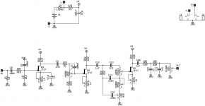
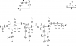
Anyway, here's the circuit snippet I've got worked up and some pics of scope readings with different JFETs.
View attachment 13991
Might be me, maybe I'm a little %$&^ed-up the head, but those integrating capacitors should be between the output and the -in terminals of the opamps. Also try CA3130 if you want something that can swing to the rails. R5 and R12 could be larger, much larger if need be. Gives R6 and R14 more leverage. The technical term is control authority.
jubal81
Well-known member
The more I think about it, the more I think the whole idea is a little %$&^ed-up in the head. Feels like I'm on Mouser shopping for the right $200K supercar someone can leave parked in their garage just in case their 1987 Chevy Corsica needs a jump start.Might be me, maybe I'm a little %$&^ed-up the head, but those integrating capacitors should be between the output and the -in terminals of the opamps. Also try CA3130 if you want something that can swing to the rails. R5 and R12 could be larger, much larger if need be. Gives R6 and R14 more leverage. The technical term is control authority.
In practicality, I think it could be an option if you're Brian Wampler and building 10,000 of these and the extra $ on parts costs less than having someone manually sort or bias JFETs. For DIY, you can get trimmer pots at Tayda for 17 cents and it takes just a few seconds to set and forget a bias voltage on the JFET gate.
I'm gonna keep tinkering with it when my parts arrive, though, just because it's an interesting puzzle to solve and could be useful for something down the road. I see what you mean on R5 and R12. Always seemed kinda wonky to me, but I was going with that diagram from Elliot Sound. I'll also experiment with those caps. I forgot those on the first go and the system wasn't working.
BTW, you think a TLC085 would be an option? 4 channels for $4.
Chuck D. Bones
Circuit Wizard
I don't think that auto-bias will totally eliminate the need to screen JFETs for production builds. When a JFET has a 6:1 Vp range (ex. 2N5457), there is no way around having to select devices that fit into a narrower range. There is an economy of scale when screening parts. If someone buys 10,000 JFETs, they can pay a couple $K to have them all run thru an automatic tester and sorted, either by the manufacturer, distributor or a 3rd party testing house. It's very common in the electronics manufacturing industry.
The mu amp circuit mostly eliminates the need to screen JFETs for Vp and Idss because the top FET sets the drain voltage and the bottom FET sets the drain current. FETs at the extreme ends of spec range can still cause problems, but no trimmers or select-in-test resistors are required.
My opinion: auto-biasing JFETs is the tail wagging the dog because JFETs don't drift. Set the bias once by selecting a resistor in test and you're done. Still, there is value in experimentation so don't let my opinions dissuade you.
To quote Friedrich Nietzsche:
“It is hard enough to remember my opinions, without also remembering my reasons for them!”
Chuck D. Bones
Circuit Wizard
BTW, you think a TLC085 would be an option? 4 channels for $4.
Those will work. If you need four channels, then it's cheaper than buying four CA3130's. For that circuit, we want an opamp that meets these criteria:
- very low bias input current -> FET input
- output can swing close to the -rail
Chuck D. Bones
Circuit Wizard
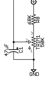
Q: What happens if you need to bias the gates more negative?So here's what I'm talking about for biasing at the JFET gates. Of course I just altered the drain resistors on my build and it sounds great. This is a solution for keeping the drain and source resistors stock.
View attachment 14499
A: The source resistor gets bigger, which consumes headroom.
I think you're better off making the source resistor a trimpot and bypassing that as req'd.
jubal81
Well-known member
Sweet! That sure simplifies things. I've always been able to gate bias, so I guess I hadn't considered that problem.Q: What happens if you need to bias the gates more negative?
A: The source resistor gets bigger, which consumes headroom.
I think you're better off making the source resistor a trimpot and bypassing that as req'd.

Chuck D. Bones
Circuit Wizard
I feel like we've come full-circle.
Similar threads
- Replies
- 0
- Views
- 145


