Servo Fuzz Face

Something is not right with this board, I can't seem to dial-in the correct bias. I'm troubleshooting it now, I'll let you all know what I find.

That frickin' CA3130 is oscillating at several hundred KHz. SHIT!
 
OK, I see what I did wrong. The CA3130's inputs should not get within 3V of the positive rail or bad shit happens. I was laboring under the misapprehension that the CA3130's input range went from rail-to-rail. The NPN version is fine as-is, but the PNP version requires a little surgery. The fix requires either a different opamp or three more resistors. Once I verify the fix, I'll post it.
 
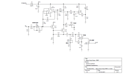
Here's the fix. New parts are R11-R14. R8 and R11-R13 should be 1%. R14 is not req'd if you are fixing an existing board, it's just there to reduce the range of Bias Trim TR1. I also increased the BIAS pot (VR5) and reduced R4 to increase the range of the BIAS pot. It works fine with VR5 = 5K and R4 = 3.3K, but I like it better this way. With the Bias Trim set to 1.5V below Vcc (7.5V if Vcc = 9V), we get symmetric clipping when BIAS is (more-or-less) at noon. With BIAS at zero, the signal is heavily gated. With BIAS dimed, there is a lot of harmonic content, but no gating.

Servo Fuzz Face PNP v1.0.png
 
Last edited:
Final rev of the PNP is v1.0, which I just updated in the post above since this is the "production" design.

Later today, I'll update and post the NPN schematic to include some minor component value changes and the addition of the 15K resistor in series with the Bias Trim pot.
 
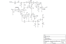
Here's the NPN version. It's very similar to the PNP version and the previous NPN version. The breadboard has been taken apart, so I can't verify it at the moment. I am starting to assemble the NPN board and will verify it when it's complete, but for now I'm calling it v0.4.

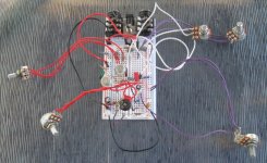
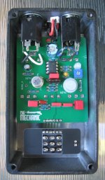
On both the PNP and NPN boards, the footprint for C6 is much smaller than the 2.2uF film caps I have, so I reduced C6 to 1uF and doubled R8 & R11 on the PNP board and R8 on the NPN board. Still very tight, but they fit, see gutshot above.

One more note: the biasing is better if Q1's HFE is below 100. This applies to both boards.

Servo Fuzz Face NPN v0.4.png
 
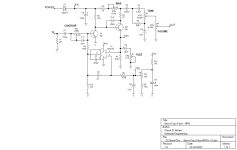
Updated NPN V1.0 schematic. This is the as-built config. I realized that a CA3140 would work in the NPN version, so I installed one of those because I have more of them and they are usually cheaper than a CA3130. R12 ensures that U1-6 can get very close to ground. I have a bunch of 10K trimpots, so I altered R9 & R10 to accommodate a 10K bias trimmer. The board footprint would not accept a 2.2uF cap for C6, so I reduced C6 to 1uF and increased R8 to 2.2M. I'm thinking a B50K might work better for the CONTOUR control. There are no pads on the board for R11, but if there were, it would be a 3.3K resistor between TR1 and R10/D2-A. When the servo loop has settled, TP1 and TP2 will be the same voltage. I have TP2 set for about 1.6V at the moment. That setting gives strong gating when BIAS is set to max resistance.

Servo Fuzz Face NPN v1.0.png

It sounds very similar to the PNP version.

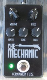
The Mechanic NPN front 02.jpg

Q1 is a blue-top MП38A.

The Mechanic NPN innards 02.jpg

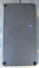
I drilled a bung-hole in the back so I can adjust the bias trim without removing the cover. That blue LED on the board lights up the inside. At this camera angle, you're seeing part of the LED in the top half of the hole and part of the trimmer in the bottom half of the hole.

The Mechanic NPN back 02.jpg
 
I was going to order a Sunflower pcb for a later build but just noticed this.. Am I right in assuming this servo FF would sound similar but with additional control over the tone and less susceptibility to temperature fluctuations?
 
Yes, but you should support your local PCB maker.
Well, I just ordered 4 pcbs from pedalpcb and have an upcoming exam and possible international move. So I am guessing about 3-4 months before I would be wanting to start any further pedals. Would it be conceivable this project might be become available as a PCB on the site in that time ??
 
Back
Top