1981 DRV (Informant)

phi1

Well-known member
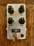
Here's one I finished a few days ago. I don't normally post my vero builds here, but my understanding is that @PedalPCB gets credit for the trace they used on the tagboard site. Why did I go to the trouble to build it on vero instead of use the easy pcb here? I like to try to fit any pedal I can in a 1590B with side mounted jacks, it's just my preference.

Mods:
1. I used 100kB for the tone (cut) knob and I reversed the lugs so it acts like most pedals (turn the knob up for more highs).
2. Bass knob is a 10kC and 1uF cap to ground (wired in between the 470ohm resistor and 220n cap). This covers down to 278Hz when the knob is all the way up (470ohm and 1uF + 220nF). The Timmy and many others have the bass knob set up to cover frequencies all the way down to the bottom of the guitar range (about 80Hz or lower). I often try to target around 300-400Hz as I find this makes the knob more useable and less boomy (an idea I got from the Rockett Blue Note and Animal).
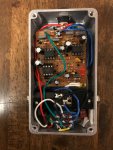
3. There's some little dip switches down by the footswitch to switch between red led clippers (on the main vero board) and 1n914s (tucked on a vero with the dip switches). I ended up setting it for 1n914s like the original.

Here's a podcast I found interviewing the designer (Matt Hoopes, who had a lot of help from the guy from Bondi Effects). It's not the most technically detailed content, but it's interesting to hear about some of the design choices. Also, it's super long. It's interesting to me personally since Emery (interviewer's band) has long been one of my favorite bands, and Relient K (builder's band) is a band I listened to in middle and high school. So it was fun for me to hear them talk about their different approaches to guitar and gear.
 

Attachments

  • IMG_0936.jpg
    IMG_0936.jpg
    947.5 KB · Views: 232
  • IMG_0934.jpg
    IMG_0934.jpg
    554.3 KB · Views: 237
Update to this one, wanted to share my experience changning from a Bass knob to a Voice knob.

Initially I built this with a Bass knob (Timmy type of configuration) (see original post). It was nice, but I didn't find myself using it that often. Since I was already taking it apart for the decal, I decided to experiment with a voice knob (like the topology in the Zendrive). I ended up liking this approach better for this particular circuit (I've used both approaches on several builds, and like them both depending on the circuit). I used a 1kC pot (lugs 2&3) in series between R8 and C5. This changes the frequency where bass is cut off, so it changes the character of the pedal (use F=1/(2piRC)). So with the voice knob maxed (same as stock circuit), frequencies below 1.5kHz are cut. With the voice knob at minimum, it's down to 492Hz. A 1kB would probably work just as well, different taper, large pot could be used to extend to lower frequencies (10k pot would get you down to 72Hz). It's a very easy mod and I would recommend folks consider it when building the Informant. You could also use a trimmer in place of R8 via the pedalpcb trimmit board.

There's a popular Rat mod called the Ruetz mod. It's a little different bc the rat circuit is a little different, but in the description there is an option to add a trimmer, which is similar to this mod.

Also, I updated the appearance. It's just a tayda bare aluminum 1590B (same enclosure as my original pic). I just dry sanded the top with 320 grit to polish it. The polish wasn't perfect, but I knew the waterslide decal would hide it, which it did. (If you just want a bare nicely polished enclosure, probably higher grit and possibly wet sand). I was inspired by a diy pedal post on TGP where a guy put actual tweed patches on top of his pedal, but the photos were really artsy and made it look black and white.
 

Attachments

  • IMG_1714.jpg
    IMG_1714.jpg
    570.3 KB · Views: 47
  • IMG_1715.jpg
    IMG_1715.jpg
    584.7 KB · Views: 46
The BASS, VOICE and RUETZ knobs all do different things. The BASS knob adds low end without affecting the middle or top end. The VOICE knob affects the gain at all frequencies and sets the bass cutoff freq. The RUETZ knob leaves the bass alone and reduces everything else. As long as the GAIN knob has sufficient range, all three will get you where you want to go because their ranges of setting have a great deal of overlap.
 
Hi Chuck, thanks as always for supplementing, well said.

There is definitely overlap in the bass and voice knob approaches. For this circuit though I thought the difference was noticeable, and I preferred the Voice knob. (Although maybe it's more in my head, since I was expecting what I would hear haha...) Since the stock cuts off at 1.5kHz, I think the Voice knob allows you to access more mids without boosting bass as much. Especially at higher gain, I felt like it makes the sound thicker, while the bass knob started to sound more muddy, or at least was harder to dial in the sweet spot. Again, I might have misjudged, since I didn't directly A/B them.

Would this be a roughly correct (but oversimplified) way to draw the differences? This is how I've been picturing it. I suppose I could try to get into LT Spice and do it properly.
1585915151092.png
*assumptions:
-The actual cut off shape is rounded
-The point where the graph cuts off the amplitude (y-axis bottom) is arbitrary
-The Voice knob also increases gain, but this is not shown, only frequency
-Depending on cap size in bass knob network, some low frequencies are always cut. This is assuming with Bass pot at max, the cutoff is below guitar frequencies
 
OK, here goes...
First, the CB Rat Bass mod. The bottom curve is a stock Rat. GAIN is at noon for all curves. Rotating the BASS control clockwise moves the frequency response up to higher and higher curves, increasing the bass at each step. Up to about 10:00, only the bass is boosted. Above that, the bass boost continues to increase and the mids start to increase as well.

Rat bass mod.PNG

Next, the Ruetz mod. This mod does not increase the bass per se, it lowers everything else. Top curve is stock. In one version Ruetz simply cut out the 47Ω resistor, which produces the bottom curve. In another version, he inserts a 1K trimpot in series with the 47Ω resistor. Image that trimpot is instead a front panel BASS pot with resistance increasing as you turn it clockwise. At zero, you get the stock freq response. As you rotate the BASS Control CW, first the highs flatten out and then the mids and the highs. GAIN is at noon for all curves.

Rat Ruetz mod.PNG

Now, the Timmy. This is very similar to the CB mod and for good reason, I pretty much copied it! Only don't call it plagiarism, call it research. ;) GAIN is at noon. The Tommy BASS control give maximum bass at zero and minimum bass at 10. Top curve is BASS at zero. I think the Timmy's BASS control would be better if it was A-taper instead of B-taper.

Timmy bass control.PNG

Finally, the Zendrive VOICE control. This VOICE control is basically another gain control that affects all frequencies at lower settings, shifting the emphasis to the upper mids as you turn it clockwise. By adjusting the VOICE and DRIVE controls in tandem, one can tailor the bass and midrange response. DRIVE control at noon.

Zendrive voice control.PNG

One thing all of these pedals have in common is they can vary the frequency response ahead of the distortion stage from a deep bass cut to a more-or-less flat frequency response. What's different is how the GAIN & BASS controls interact and how much gain and bass are available at the max settings.
 
He’s likely referring to this post (or something similar). His bass mod is a few posts down.


Thanks for taking the time to put this together. It is super helpful to visualize.

I should have been more clear that my excel graph of the Voice knob is assuming you compensate with the gain knob, since I was mainly interested in the control over the low frequencies, and gain can be adjusted after you dial in the bass cut. Anyway, it’s better / more intuitive to show them how you have them, how the voice knob itself actually affects things. Plus it’s great to see the actual curves, rather than just plugging in the formula. Thanks again for that.
 
OK, here goes...
First, the CB Rat Bass mod. The bottom curve is a stock Rat. GAIN is at noon for all curves. Rotating the BASS control clockwise moves the frequency response up to higher and higher curves, increasing the bass at each step. Up to about 10:00, only the bass is boosted. Above that, the bass boost continues to increase and the mids start to increase as well.

View attachment 3830

Next, the Ruetz mod. This mod does not increase the bass per se, it lowers everything else. Top curve is stock. In one version Ruetz simply cut out the 47Ω resistor, which produces the bottom curve. In another version, he inserts a 1K trimpot in series with the 47Ω resistor. Image that trimpot is instead a front panel BASS pot with resistance increasing as you turn it clockwise. At zero, you get the stock freq response. As you rotate the BASS Control CW, first the highs flatten out and then the mids and the highs. GAIN is at noon for all curves.

View attachment 3831

Now, the Timmy. This is very similar to the CB mod and for good reason, I pretty much copied it! Only don't call it plagiarism, call it research. ;) GAIN is at noon. The Tommy BASS control give maximum bass at zero and minimum bass at 10. Top curve is BASS at zero. I think the Timmy's BASS control would be better if it was A-taper instead of B-taper.

View attachment 3832

Finally, the Zendrive VOICE control. This VOICE control is basically another gain control that affects all frequencies at lower settings, shifting the emphasis to the upper mids as you turn it clockwise. By adjusting the VOICE and DRIVE controls in tandem, one can tailor the bass and midrange response. DRIVE control at noon.

View attachment 3833

One thing all of these pedals have in common is they can vary the frequency response ahead of the distortion stage from a deep bass cut to a more-or-less flat frequency response. What's different is how the GAIN & BASS controls interact and how much gain and bass are available at the max settings.
Very cool! What program / tonestack simulator are you using for that? Thanks for the insights! I might have some questions regarding two circuits for you to unpick if you don't mind... Probably best to start a new thread or should I post here? Cheers!
 
You can post here. I used LTSpice. If you're not familiar, it's a free circuit simulator originally provided by the IC manufacturer Linear Technologies. Analog Devices bought Linear Technologies a few years ago and continues to host/support LTSpice. SPICE has been around since the late '60s and has continuously improved over the decades. It is remarkably accurate. I always run sims on my designs and mods before and during breadboarding.
 
I should have been more clear that my excel graph of the Voice knob is assuming you compensate with the gain knob, since I was mainly interested in the control over the low frequencies, and gain can be adjusted after you dial in the bass cut.

I knew that's what you meant. (y)
 
You can post here. I used LTSpice. If you're not familiar, it's a free circuit simulator originally provided by the IC manufacturer Linear Technologies. Analog Devices bought Linear Technologies a few years ago and continues to host/support LTSpice. SPICE has been around since the late '60s and has continuously improved over the decades. It is remarkably accurate. I always run sims on my designs and mods before and during breadboarding.
Awesome, thanks for the info! I have only just started using one called simply "Tonestack calculator" but the LT Spice looks better and of course knowing how to use it and having practise with it...
On that note, could you look into and explain me the tone stack of Ember Boost (TC Spark boost), snippet of tone stack here. It looks a bit fawnkeee to me and not what I would suspect in a Baxendal stack or what am I missing here? The typical way a Baxendal would be is that in place of resistors R 20 and R24 there would be caps and C16 would not be there (jumpered), right? In any case, I'm not quite happy how the Ember boost sounds, I'd like also more treble and less bass and the tone stack doesn't seem to work really that well, what's your recommendation, Chuck?
KTjfx9F.jpg


Same story of I'd like less bass and more treble on SoftII tone stack and I don't feel that it's flat when both are set at noon, it seems too bass heavy. Or is there other things in pedal that need to be changed to get more treble/less bass? Initially I thought it's just part of the circuit but I'd like to tweak it and I think there was someone else on the forum here who had the same idea.

armfrYz.jpg


Thanks for your time looking into this, Chuck or anyone else who wants to chime in!
 
There are a few variations on the Baxandall tone stack, one of which is as you noted, R20 and R24 are replaced by capacitors and C15 is replaced by a resistor. C19 is usually not there. It rolls off some of the treble content. You are correct in stating that the overall frequency response in controlled by more than just the tone stack. I usually simulate the entire circuit circuit so the effects and interactions from each section of the circuit can be evaluated. Makes it much easier to see which parts can be modded to achieve the desired results. A listening test is always the final confirmation whether the desired tone is achieved. It's late, so I'll run some sims on Tues and present the results and hopefully, some recommendations of mods to try.
 
There are a few variations on the Baxandall tone stack, one of which is as you noted, R20 and R24 are replaced by capacitors and C15 is replaced by a resistor. C19 is usually not there. It rolls off some of the treble content. You are correct in stating that the overall frequency response in controlled by more than just the tone stack. I usually simulate the entire circuit circuit so the effects and interactions from each section of the circuit can be evaluated. Makes it much easier to see which parts can be modded to achieve the desired results. A listening test is always the final confirmation whether the desired tone is achieved. It's late, so I'll run some sims on Tues and present the results and hopefully, some recommendations of mods to try.
Awesome, no rush! Much appreciated help and of course the full schematics are on the pedalpcb site as referred to. Cheers!
 
Here's the Ember Boost tone control freq response. This is just the tone control stage. You can see effects of C19 rolling the treble off above 5KHz. If you want more Presence, then remove C19. This tone stack could have a wider control range. R20 limits the treble boost and R24 limits the treble cut. R21 limits the bass boost and R23 limits the bass cut.

TC elec spark boost tone controls.PNG

There is additional tone shaping before and inside the distortion stage. C6 rolls the treble off at 1.6KHz, but only when SW1 is up or down. It has no effect when SW1 is in the middle position. C10 rolls the treble off at 1.6KHz when the GAIN is at minimum and at 800Hz when the GAIN is at maximum. If you want more treble, I'd try adjusting C10 before you go messing with the tone controls. You say "...the tone stack doesn't seem to work really that well...", I'm not sure I know what you mean. If you mean that you can't recover enough of the lost treble, then remove C19 and reduce C10. If you mean something else, please be more specific. C7 & C8 control how much bass gets into the distortion stage. C7 rolls off the bass below 185Hz and C8 rolls off the bass below 408Hz. I you want more bass going into the distortion stage, then make one or both of them bigger. SW1 selects which capacitor (or neither) is in the circuit. It's kind of a Mid Boost switch.
 
Awesome Chuck! Yes this is a good description of what I'm missing : "If you mean that you can't recover enough of the lost treble, then remove C19 and reduce C10. "
And I'll give that a go and will let you know. Cheers, very enlightening!
 
Getting back to the SOFTii...
The tone controls are not flat when set at noon. Even if they were, other parts of the circuit do not have a flat frequency response, so you will never be able to achieve a flat frequency response with the SOFTii. Same goes for guitar amps, and for good reason. An electric guitar played thru a hi-fi (low distortion, flat freq response) amplifier sounds pretty thin. Try it and you'll see what I mean.
Anyway... for the James tone control in the SOFTii to have a flat setting, R11 would have to be 10x larger than R14 (it's not). C8 would have to be 10x smaller than C9 (it's not). C6 would have to be 10x smaller than C7 (you noticing a trend here?). Catalinbread designed the SFT tone stack to mimic the overall response of the large Ampeg amplifiers.

Duncan's Tone Stack Calculator simulates the James tone stack, so let's plug in the values and see what we get. For the source impedance, Zsrc, i'm gonna guess 10K. It's probably lower, but making it lower doesn't really affect the response. With the controls centered, there is a 2dB bump around 250Hz and a 1dB drop in treble above 2KHz. Both would be barely audible. Bass goes up and down 20dB. Treble goes up 18dB and down a bottomless pit below 1. The treble control affects the mids quite a bit and might be why Cooder can't dial in the tone he wants. I suggest playing with the Tone Calculator to see how changing C6 and C7 affects the response, that might provide a clue as to what to change to get the desired tone.

The other place I'd look is R21 & C14. Those two parts roll off the treble at 1KHz. Try shorting out R21 and see if that sounds better.
 
Back
Top