MichaelW
Well-known member
- Build Rating
- 5.00 star(s)
So first off let me start by saying this is a freaking awesome sounding pedal.....and there's a reason for that, which I'll get to in a bit.
Secondly, let me say this is not really the "fuzz" that I was expecting to build.
I guess there was quite a bit of discussion about this circuit in a thread that I actually participated in....yet I missed the whole point....hahahaha.....(I think I'm starting to understand why my wife is always so frustrated with me....... )
)
For some reason I had it in my head that the Lovepedal 200lbs of Gold was an Si FF into a TS (a la the Grover/Dover Drive) but in a dual pedal format single enclosure. And I thought that the 5lbs of Gold iteration from @Robert was just the fuzz side of that dual pedal. When I ordered the 5lb board I thought I was just getting an Si fuzz and was planning to pair it up with a Zen Drive to have the two halves in separate boxes for more flexibility. It would also let me pair it up with a more authentic TS type pedal like the Soloist or Greengage, CKK Scream Honey, etc.
I should probably spend a bit more time reviewing the schematics of my builds before building heh. So it turns out that the Lovepedal 200lbs of Gold actually IS a Dover drive, just re-packaged with some very minor component changes and an added boost. They are essentially the same circuit, a silicon Fuzz Face into a Zen drive where the Zen is preset at 50% gain and there's a bias trimmer for the fuzz side.
So gee, a pedal maker re-packaging their own pedal and selling it as something new.....why is this not surprising......
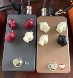
When I built my Grover drive I converted it into a 4 knob format and exposed the internal FF bias trimmer so I could have more control over the different sounds by playing with the fuzz bias. You can dial it from super smooth to gated and starved. Some very cool sounds you can get. Since I didn't know that the 5lb was basically the same pedal until after I had already built it and was asking @Robert a question about biasing I was like "Dang, I should have done the same thing as the Grover and exposed the bias trimmer as an external control!" (I still might).
So back to my initial statement of why this sounds so awesome, the Grover drive is one of my favorite overdrives and has not left my pedal chain since I built it.
I absolutely love it. I love the Zen drive but I also tire of it pretty quickly. As an analogy, the Zen Drive is like eggnog, where the Grover/Dover is like eggnog with a shot of Myers Dark Rum in it. The addition of the FF just gives the Zen a lot more character than the Zen alone. Being able to tweak the FF bias is like the whipped cream on top of the eggnog.... .
.
So once I learned all this, I started comparing the 5lb Bag of Gold next to the Grover and they are extremely similar. The "fuzz" control on both pedal blends in the amount of the FF into the fixed Zen drive gain setting. If I turn the fuzz knob all the way down on both pedals they are virtually identical. The 5lb sounds a tad meatier (and I think I know why).
The 5lb has an extra 100nf cap going to ground in the otherwise identical Zen-type clipping circuit (comprising of a mix of Bat46, Ge and Mosfet clippers).
The Grover/Dover is missing this cap. Curiously, the Grover/Dover has a 100nf input cap that I believe is a mistake in the schematic that has been continued to be propagated as other board makers are offering this circuit. (The MadBeans "Cliffhanger" includes this input cap, for instance). This 100n input cap should be omitted if you are building the Grover. It causes a LOT of noise and serves no purpose whatsoever. (Hence why I think it's a mistake).
As @music6000 pointed out in the thread I referenced above, the 5lb circuit is just the Dover circuit turned 180 degrees.
Anyway, as surprised as I was that I didn't build a cool fuzz like I was expecting to today, I am totally digging the 5lb Bag of Gold.
So if you happen to be sitting on the fence of whether to build a Grover drive, I'd recommend building the 5lb Bag of Gold if you want a bit meatier sound and a spittier fuzz capability. Or build the Grover if you want a more "leaner" sound and more smoother capabilities. Or better yet, build both
I would also recommend exposing the internal trimpot on both builds with a B10k and be able to adjust the Fuzz bias without needing to take the back off, there's a lot of very usable cool and different sounds by just adjusting the Fuzz bias.
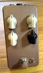
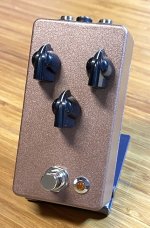
For this enclosure, since I have no more powdercoated Gold 1590B's, I decided to use the same rattle can as I used on my PowerSound Overdrive pedal.
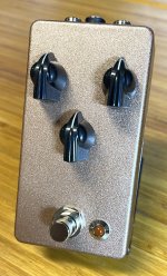
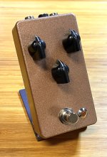
It's called "Aged Copper" but looks gold to me. (Since because...well....it's a 5lb Bag of GOLD innit?) I decided to paint the whole enclosure, and unfortunately, I painted it in the driveway after the sun went down last night to give it overnight to dry and did not see that it did a little bit of "spitting". But overall I think it turned out well and I'm happy with the way it looks.
Question is, am I going to plug the holes and re-drill it for a 4 knob mod or not? heh.....dunno yet. Since I already have the Grover, I can get those sounds from that pedal. But, but, but.....I feel like something's missing....a mod that calls for attention....sigh. We'll see.
I built this to spec. The only sub I made was the Ge diode, instead of a 1n34A I used one of the ITT Red Band diodes that I've been prattling on about. Really great sounding 1N34A substitution.
A couple of different angles and lighting to show off the color.
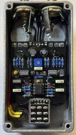
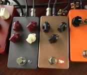
And here it is in action side by side with my Grover build comparing.....they are extremely similar sounding.
Secondly, let me say this is not really the "fuzz" that I was expecting to build.
I guess there was quite a bit of discussion about this circuit in a thread that I actually participated in....yet I missed the whole point....hahahaha.....(I think I'm starting to understand why my wife is always so frustrated with me.......
For some reason I had it in my head that the Lovepedal 200lbs of Gold was an Si FF into a TS (a la the Grover/Dover Drive) but in a dual pedal format single enclosure. And I thought that the 5lbs of Gold iteration from @Robert was just the fuzz side of that dual pedal. When I ordered the 5lb board I thought I was just getting an Si fuzz and was planning to pair it up with a Zen Drive to have the two halves in separate boxes for more flexibility. It would also let me pair it up with a more authentic TS type pedal like the Soloist or Greengage, CKK Scream Honey, etc.
I should probably spend a bit more time reviewing the schematics of my builds before building heh. So it turns out that the Lovepedal 200lbs of Gold actually IS a Dover drive, just re-packaged with some very minor component changes and an added boost. They are essentially the same circuit, a silicon Fuzz Face into a Zen drive where the Zen is preset at 50% gain and there's a bias trimmer for the fuzz side.
So gee, a pedal maker re-packaging their own pedal and selling it as something new.....why is this not surprising......
When I built my Grover drive I converted it into a 4 knob format and exposed the internal FF bias trimmer so I could have more control over the different sounds by playing with the fuzz bias. You can dial it from super smooth to gated and starved. Some very cool sounds you can get. Since I didn't know that the 5lb was basically the same pedal until after I had already built it and was asking @Robert a question about biasing I was like "Dang, I should have done the same thing as the Grover and exposed the bias trimmer as an external control!" (I still might).
So back to my initial statement of why this sounds so awesome, the Grover drive is one of my favorite overdrives and has not left my pedal chain since I built it.
I absolutely love it. I love the Zen drive but I also tire of it pretty quickly. As an analogy, the Zen Drive is like eggnog, where the Grover/Dover is like eggnog with a shot of Myers Dark Rum in it. The addition of the FF just gives the Zen a lot more character than the Zen alone. Being able to tweak the FF bias is like the whipped cream on top of the eggnog....
So once I learned all this, I started comparing the 5lb Bag of Gold next to the Grover and they are extremely similar. The "fuzz" control on both pedal blends in the amount of the FF into the fixed Zen drive gain setting. If I turn the fuzz knob all the way down on both pedals they are virtually identical. The 5lb sounds a tad meatier (and I think I know why).
The 5lb has an extra 100nf cap going to ground in the otherwise identical Zen-type clipping circuit (comprising of a mix of Bat46, Ge and Mosfet clippers).
The Grover/Dover is missing this cap. Curiously, the Grover/Dover has a 100nf input cap that I believe is a mistake in the schematic that has been continued to be propagated as other board makers are offering this circuit. (The MadBeans "Cliffhanger" includes this input cap, for instance). This 100n input cap should be omitted if you are building the Grover. It causes a LOT of noise and serves no purpose whatsoever. (Hence why I think it's a mistake).
As @music6000 pointed out in the thread I referenced above, the 5lb circuit is just the Dover circuit turned 180 degrees.
Anyway, as surprised as I was that I didn't build a cool fuzz like I was expecting to today, I am totally digging the 5lb Bag of Gold.
So if you happen to be sitting on the fence of whether to build a Grover drive, I'd recommend building the 5lb Bag of Gold if you want a bit meatier sound and a spittier fuzz capability. Or build the Grover if you want a more "leaner" sound and more smoother capabilities. Or better yet, build both
I would also recommend exposing the internal trimpot on both builds with a B10k and be able to adjust the Fuzz bias without needing to take the back off, there's a lot of very usable cool and different sounds by just adjusting the Fuzz bias.
For this enclosure, since I have no more powdercoated Gold 1590B's, I decided to use the same rattle can as I used on my PowerSound Overdrive pedal.
It's called "Aged Copper" but looks gold to me. (Since because...well....it's a 5lb Bag of GOLD innit?) I decided to paint the whole enclosure, and unfortunately, I painted it in the driveway after the sun went down last night to give it overnight to dry and did not see that it did a little bit of "spitting". But overall I think it turned out well and I'm happy with the way it looks.
Question is, am I going to plug the holes and re-drill it for a 4 knob mod or not? heh.....dunno yet. Since I already have the Grover, I can get those sounds from that pedal. But, but, but.....I feel like something's missing....a mod that calls for attention....sigh. We'll see.
I built this to spec. The only sub I made was the Ge diode, instead of a 1n34A I used one of the ITT Red Band diodes that I've been prattling on about. Really great sounding 1N34A substitution.
A couple of different angles and lighting to show off the color.


And here it is in action side by side with my Grover build comparing.....they are extremely similar sounding.


