
You are using an out of date browser. It may not display this or other websites correctly.
You should upgrade or use an alternative browser.
You should upgrade or use an alternative browser.
6 Band EQ formula?
- Thread starter irvmuller
- Start date
benny_profane
Well-known member
The circuit comprises multiple bandpass gyrators. You can use this calculator to adjust the values to change the affected frequencies.
Chuck D. Bones
Circuit Wizard
Keep R2 above 470Ω and the ratio of R1/R2 <100. There are four parts you can fiddle to change two parameters (F & Q), so there are many solutions.
irvmuller
Active member
Chuck D. Bones
Circuit Wizard
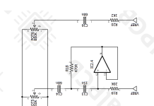
That last filter is a high-pass or low-pass filter, depending on whether POT1 is above or below noon. It is a shelving filter, which means that above the cutoff freq, the gain is flat. The cutoff freq is determined by R20 & C16 using the usual formula. R20 determines the max cut or boost, so if you only want to change the cutoff freq, leave R20 alone and vary C16.
BTW, that Gyrator formula website leaves out an important piece of information: The impedance at resonance. That impedance determines the max boost or cut. In the case of the 6-Band EQ, the 470Ω resistors determine that impedance.
BTW, that Gyrator formula website leaves out an important piece of information: The impedance at resonance. That impedance determines the max boost or cut. In the case of the 6-Band EQ, the 470Ω resistors determine that impedance.
Mike McLane
Active member
I mentioned something some time back about a "Tom Bukovac version" where the the bands were focused on the mid ranges.

Anybody have any interest in that?
Anybody have any interest in that?
")
benny_profane
Well-known member
What modifications would be required to preserve the frequency bands while changing the pot values to B100k?
Chuck D. Bones
Circuit Wizard
The pot value doesn't affect the center frequency of each band. It does affect the smoothness of the sweep. If you want to keep the same feel, then scale all of the impedances up by 2x. That means doubling resistors and halving capacitors. This includes all of the components in the gyrators, R6 and R7.
You know I love building pedals, but sometimes I punt & buy one of the Chinese knockoffs. I bought a Caline CP-24 10-band EQ pedal for $37 four years ago on the big A.
You know I love building pedals, but sometimes I punt & buy one of the Chinese knockoffs. I bought a Caline CP-24 10-band EQ pedal for $37 four years ago on the big A.
benny_profane
Well-known member
Thanks @Chuck D. Bones
I actually went that way myself too (MXR 10-band on wild sale though). I’m thinking about a combo build here though and would like to have the EQ control integrated.
I actually went that way myself too (MXR 10-band on wild sale though). I’m thinking about a combo build here though and would like to have the EQ control integrated.
Feral Feline
Well-known member
Cross-referencing for people looking to mod the 6-band:
 forum.pedalpcb.com
6 Band EQ Mods
I would like to know if there are are any ways to modify the 6 band EQ. Change the frequency of a knob? Quiet component recommendations?
Chuck D. Bones
Circuit Wizard
I’m thinking about a combo build here though and would like to have the EQ control integrated.
I take it you've already tried this out by stacking the EQ with the other circuit you have in mind. Do you plan on putting the EQ up front or at the end?
Feral Feline
Well-known member
Stick it on a flip-flop so you can have EQ before or after the main circuit.
benny_profane
Well-known member
Yep. A breadboarded version of the Unicab with the MXR ten-band—not the ppcb six-band. Planning on having it be a desktop end-of-chain interface with the EQ for adjustments before the cab sim.I take it you've already tried this out by stacking the EQ with the other circuit you have in mind. Do you plan on putting the EQ up front or at the end?
Last edited:
Chuck D. Bones
Circuit Wizard
As long as you don't overdrive the Unicab or the EQ, the order won't matter.
caspercody
Active member
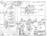
I would like to re-create the ADA MP1 eq section using this pedal PCB, and only using (4) of the (6) pots. The frequencies, i believe are:
Treble - 1.6k
Mids - 600
Bass - 160
Presence - 3k
Would it be fairly easy to switch some values to get these frequencies? I tried plugging in different cap values in the calculator link above, to try and get close to the Bass 160hz. But, would just changing the cap values alter the pot sweep?
I have attached a file showing the eq portion of the ADA MP1, and someone hand wrote in the frequencies.
Thanks
Rob
Attachments
Chuck D. Bones
Circuit Wizard
They sure made it complicated! With a multi-band EQ, we have three variables:
1. Center Freq
2. Q (bandwidth)
3. Gain at Center Freq (sort of related to Q, but can be varied independently)
Depending on how accurately you want to replicate the freq response on the MP1, you have to match all three variables for each band.
The MP1 BASS filter is 1st-order and doesn't have a Q.
What are the requirements for your build?
1. Match only the center freqs
2. Match all three to the greatest extent
It's all doable, it's just a matter of analyzing the MP1 filters and then altering the PPCB component values. There will also be some cut & jumpering.
Should I ask why you want to do this?
caspercody
Active member
I want to be as accurate as possible
With all the preamps I have made, to my ears the distortion is basically the same, just different levels of gain. And what seems to be the difference between the amps is the tone stacks. I love 80’s Rome (Extreme, white Lion), so I wanted to try to create that MP1 tone stack
I made a tube/IC pedal, but it is very noisy. Now just want to try tone stack in a pedal after a distortion
caspercody
Active member
Is it possible to use the Pedal PCB board, and just change some components values to get to the same frequencies? I do not want to convert the pedal PCB to match the MP1 schematic, just throwing that out there based on your comment about jumpers and cuts....
Chuck D. Bones
Circuit Wizard
If all you want is to match the center freq & approximate the Q, then all you have to do is change some component values. I wasn't even contemplating replicating the MP1 circuitry, just making the approximation more accurate.
Let me ask you this: do you have or can you borrow a 6- 8- or 10-band EQ? Might be enlightening to see what settings produce the tones you want before we try butchering an existing design.
Let me ask you this: do you have or can you borrow a 6- 8- or 10-band EQ? Might be enlightening to see what settings produce the tones you want before we try butchering an existing design.
Similar threads
- Replies
- 1
- Views
- 171