A friend and I have been building true Rockman X100 clones that will run off a standard negative center 9V @ 500mA wall-wart. We learned very fast that standard chargepumps cannot supply enough current.
What we did find was a nifty little buck converter module on
LINK: eBay and
LINK: Amazon. We bought from both sources and they are reliable.
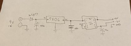
The
MP1584EN in these modules is unique in that two of them can be fed the same 9V DC supply, and tho wired together (to get the ±6v dual rail supply with enough current on both sides) unconventionally, the diagram below shows how to with the BC modules to gather to set a solid, quiet, lo-ripple ±6V dual-rail DC supply pair at over 500mA each. Once they are wired together, connect a 9V battery at eh + In and the ground inputs. Then put a DC voltage meter on the output of each one, one at a time and tweak the tiny trimpot to set the output for +6V and -6V respectively. Use a tiny plastic tipped flat-head screw driver - those trimmers are all metal and quite small. It may take a few tries to nail ±6.00 when adjusting the trimmers. It's OK if they are within 0.05V of the ±6.00V
These BC modules are quite versatile in that they will provide the same voltage whether loaded or not. The current available varies on the input supply and output yield as set by the trimmers. At +9V DC in and ±6V DC out (+6V on one module & -6V on the other), the available current exceeds 1A. More than enough to drive a Rockman.
I often use this to modify Rockman HP gear.
View attachment 44857
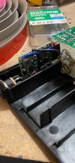
We went so far as to have some mounting daughterboard PCBs fabricated to accommodate the two BC modules for our Rockman X100 builds for quicker assembly.
View attachment 44860
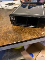
And just for the heck of it, some shots of our RMS X100 builds . . .
(In the the 3rd shot, you can see the mounted BC module PCB.)
View attachment 44861 View attachment 44862 View attachment 44863