BuddytheReow
Breadboard Baker
Hey guys,
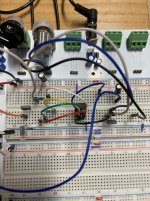
I hate to ask your help, but I've been trying for a few days to get a simple Non-inverting opamp to work. This is the Distortion 250 without diode clipping. I used to build this one in my sleep 6 months ago, but now nothing. I guess I've been too busy soldering and designing transistor circuits for Chuck's contest, LOL. Anyway, I've breadboarded it and taken it apart at least 4 times now and for the life of me I can't get it to work . I either get no signal, a very "starved" sound, or unity gain. The gain knob doesn't work. Here is a picture of the breadboard. I hope you all can see it clearly. I do have signal going into the opamp so that part's good. Here's also the schematic. Please read to the end. There are lots of pictures.

The top part is the voltage divider and R5. All 1M (I checked before installing and they are within tolerance). The weird part is when I check the voltage right at the divider I get about 2.5 volts. Seem kind of odd, right?
The bottom left is the input section. A 10n cap into a 1k resistor with a 1m resistor going to ground. The red jumper then goes into the non-inverting opamp (pin 3).
The bottom middle is the feedback loop. Jumpered from the - Input to a 1m resistor and then going to the output with the black jumper. To complete the feedback loop I've got a 47n cap to the gain pot (1m) on lugs 2 and 3. Lug 3 goes to the 4.7k resistor. I know the order is backwards but I don't think that makes a difference?
The output goes to a 1u electro cap and then to my output signal.

At first I thought it was the breadboard and checked continutity on all the rows/columns (a real pain). Then I built this again on a different breadboard with no luck. Here are my IC voltages:
1 0
2 1.92
3 1.11
4 0
5 0
6 1.97
7 9
8 0

As you can see I have it chip powered correctly (pin 7 is 9v and pin 4 is 0). I am wondering about the other voltages here.
I hate to ask your help, but I've been trying for a few days to get a simple Non-inverting opamp to work. This is the Distortion 250 without diode clipping. I used to build this one in my sleep 6 months ago, but now nothing. I guess I've been too busy soldering and designing transistor circuits for Chuck's contest, LOL. Anyway, I've breadboarded it and taken it apart at least 4 times now and for the life of me I can't get it to work . I either get no signal, a very "starved" sound, or unity gain. The gain knob doesn't work. Here is a picture of the breadboard. I hope you all can see it clearly. I do have signal going into the opamp so that part's good. Here's also the schematic. Please read to the end. There are lots of pictures.
The top part is the voltage divider and R5. All 1M (I checked before installing and they are within tolerance). The weird part is when I check the voltage right at the divider I get about 2.5 volts. Seem kind of odd, right?
The bottom left is the input section. A 10n cap into a 1k resistor with a 1m resistor going to ground. The red jumper then goes into the non-inverting opamp (pin 3).
The bottom middle is the feedback loop. Jumpered from the - Input to a 1m resistor and then going to the output with the black jumper. To complete the feedback loop I've got a 47n cap to the gain pot (1m) on lugs 2 and 3. Lug 3 goes to the 4.7k resistor. I know the order is backwards but I don't think that makes a difference?
The output goes to a 1u electro cap and then to my output signal.
At first I thought it was the breadboard and checked continutity on all the rows/columns (a real pain). Then I built this again on a different breadboard with no luck. Here are my IC voltages:
1 0
2 1.92
3 1.11
4 0
5 0
6 1.97
7 9
8 0
As you can see I have it chip powered correctly (pin 7 is 9v and pin 4 is 0). I am wondering about the other voltages here.
Last edited:
")