SOLVED Abider drive J201 Issues???

Hi again Gang,
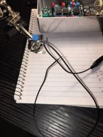
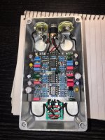
So having built an abider before and liked it a lot, a friend of mine wanted one. Just building one now and the pedal is fine when 'off' but when I engage the foot switch all I get is a quiet white noise. I changed the chips to see if it was them as they were the only thing's I didn't 'test' before soldering them (socketed).

Im now wondering if the switch could be the culprit?. Good quality Gorva. Do you think I burnt it out by soldering it. I don't think I applied excessive heat to it but this is the first time Ive really had a problem like this...
Can you help?.
I did try to upload a small audio file(mp3 ~ 700b - 10 seconds) but alas it wouldn't let me when I tried to attach file.

Anyone!?!?!?!
 

Attachments

  • image.jpg
    image.jpg
    609.3 KB · Views: 34
Solution
Where'd you get those 4558 opamps?

They look a little odd.

Do you by any chance have another set of known good opamps?

While we're on that subject, where'd you get your J201 transistor?
Use a DMM to test the continuity between the lugs, and then the lugs to the jacks. That will tell you if something in the switch has been damaged.
Thanks, Ive just tested the lugs and the jacks with a DMM and they all seem to be correct and switching appropriately....

The board is getting power when switched on and the LED comes on. Ive chased the wiring and it all seems to be in the right place?????...
As I said I tested all the components before putting them in????. are there any other good 'test points' that would be able to narrow this down a little?.
Thanks for the responses.
 
I'd check the voltages of your op amps and the jfet to see if any of those look off. Since it seems more likely that your output is working due to the noise, you could start with an audio probe inserting signal into the circuit to see where it drops out. Also I've never seen jrc4558s that look anything like that, so maybe swapping different dual op amps might be worth a shot.
 
Last edited:
I'd check the voltages of your op amps and the jfet to see if any of those look off. Since it seems more likely that your output is working due to the noise, you could start with an audio probe inserting signal into the circuit to see where it drops out. Also I've never seen jrc4558s that look anything like that, so maybe swapping different dual op amps might not be worth a shot.
Hmmm... Would you be able to tell me where I would be able to check the voltages?...
I think I remember reading that I can take the voltage of the top chip at the stripe end of the 5817 Shotkey = 9.13v (??? isn't there a charge pump/ should be closer to 18v surely????)
Not sure how to check the lower two?

voltage on J201 is 9.07v - tested on M-meter at 391hfe I think from memory.
voltage on 2N3904 is 3.33v (this doesn't sound right either for some reason????) tested about 200Hfe on my M-meter.

I don't have an audio probe...

And with regards the chips... I have another stash that I bought from a reputable dealer and I changed all of them out and it doesn't help.
Still the same.

How do I test the voltages on the lower two chips?.

Thanks again for your kind attn.
 
Where'd you get those 4558 opamps?

They look a little odd.

Do you by any chance have another set of known good opamps?

While we're on that subject, where'd you get your J201 transistor?
Hi Robert,
Thanks for taking the time. I got the 4558's (bottom two in the pic) of a company on eBay (I know - they look fake chinese to me too), I was very sceptical about them but they worked for the last abider I made, and sounded killer.... the ones that are in it now are all the same as the top one but all fresh out of the box... I got them from a company called BitsBox.co.uk, Ive used them for a long time for bits like this. They have always been top notch!.

With regards the J201. Again I used the same company I did last time with stellar results... BitsBox.co.uk
 
You can make an audio probe with a jack and a 100n (or anything really, its just to block DC voltage from your device/guitar inputting signal) capacitor, and if you don't have a spare jack, you could even desolder your lead from your input jack and put a capacitor on that to inject some signal into the circuit after stages to see where you're not getting it through.


Do you have another j201 from the same batch to test again to see if it reads hfe like a BJT?
Ive got tons of spare jacks!... ;)... and a 100n cap. how do I make this magic probe you speak of???. and I'm not sure I got the explanation there?... I would love to try that tho!...

And no, I don't have another J201... but obviously could get another in a few days if you guys think that's the problem???
 
You just need a wire to connect to ground as per usual, and then the tip of the jack connects to the 100n cap, and then you have a probe/wire thats free that you use to poke around and insert your guitar/signal into the circuit while the output jack from the pedal goes to an amp. You can do it the same the opposite way if you suspect your signal isnt making it to the output, you just run your guitar/signal into the normal input jack and then use the probe you made going to your amp and poke around to see where your signal is getting lost. I'll look at the abider circuit and give you some places to poke in a bit.
 
I'd try inserting signal/guitar (with the wire from your capacitor attached to the tip of your jack and with the sleeve of the jack grounded to the circuit) at the center pin of the j201, and pin 3 of all the op amps, that should eliminate portions of the circuit to troubleshoot.
 
You just need a wire to connect to ground as per usual, and then the tip of the jack connects to the 100n cap, and then you have a probe/wire thats free that you use to poke around and insert your guitar/signal into the circuit while the output jack from the pedal goes to an amp. You can do it the same the opposite way if you suspect your signal isnt making it to the output, you just run your guitar/signal into the normal input jack and then use the probe you made going to your amp and poke around to see where your signal is getting lost. I'll look at the abider circuit and give you some places to poke in a bit.
Im hoping the attached pic is close to what you described!... I'll give those test points a try!...
Thanks again for your help here fella... Much appreciated!.
 

Attachments

  • image copy.jpg
    image copy.jpg
    543.4 KB · Views: 8
Back
Top