Arkaim fuzz left led has power all the time…

PAGOON

Active member
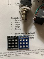
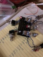
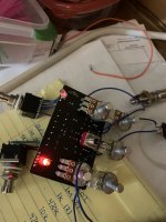
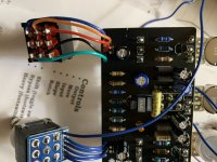
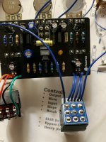
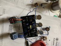
Hello everyone I just completed a Arkaim fuzz and I’m not sure if it’s working correctly… I was bench testing it and I noticed that the led has power when I don’t think it should. The led was dim… I saw other posts about wiring but I pretty sure I did it correctly… I thought may have had the gnd and sw switched around but I re did that and that wasn’t the case. The only screwy thing was I didn’t have a 12n cap so I went to the electronics store and got a .012uf odd type capacitor.
 

Attachments

  • 296A922A-F640-4A64-8501-8184F057544A.jpeg
    296A922A-F640-4A64-8501-8184F057544A.jpeg
    411.7 KB · Views: 16
  • EEFFDEDC-095D-4B22-AB01-0821F5C57BCC.jpeg
    EEFFDEDC-095D-4B22-AB01-0821F5C57BCC.jpeg
    398.2 KB · Views: 17
  • 656D61DB-7473-4888-9A2A-62147E2896FC.jpeg
    656D61DB-7473-4888-9A2A-62147E2896FC.jpeg
    361.4 KB · Views: 16
  • 5F934B4B-8035-4CEC-8FEF-4B2A09BEC42F.jpeg
    5F934B4B-8035-4CEC-8FEF-4B2A09BEC42F.jpeg
    368.8 KB · Views: 18
  • 83062079-7600-46F8-AD1A-FE25A2CBA012.jpeg
    83062079-7600-46F8-AD1A-FE25A2CBA012.jpeg
    352.2 KB · Views: 15
Usually stuff like this happens when you have a short. I can’t really see the solder side of either the main or breakout board, maybe a wire strand is shorting?
 
The LED and GND on the two breakout boards are swapped, I'm not sure if that is what is causing your issue though.
I thought of that and swapped the two middle wires from the switch ….. it made things worse…. The pedal plays fine and all but that led stays on no matter what it’s a bit bassy pedal and the boost switch or heavy isn’t working really and the led who’ll get brighter when I turn the input knob up… I’m wondering if I mounted my electrolytic capacitors to close to the board and maybe the solder dripped on the positive side and is causing a short…!
 
The LED and GND on the two breakout boards are swapped, I'm not sure if that is what is causing your issue though.
They should be labeled on the board and in the building documents…
Did you mount the breakout backwards?
naw but I’ve seen the gnd and sw moved around before it sucks it should be labeled in the building documents it’s probably because I used this 3pdt board … I put my voltmeter to check Continuity on the grounds and I undid the wire is going to the PCB to see which ones pinged for grounds
 
If the volume knob controls the LED brightness something is most likely going on with the 3PDT wiring.

The OUT pad of the PCB has most likely somehow become connected to the SW pad, either by an unintentional short or something on the breakout board. This makes the Volume pot a variable current limiting resistor for the LED.
I was thinking that I should have never used this 3pdt board and just followed how it is in the directions but I thought I’d be good with one 3pdt board on that one side … NOTE I CHANGED THE C100 CAPACITOR AND SWAPED THE TWO WIRES ON THE SWITCH WITH THE BOARD (THE GND AND SW ) and it’s working GREAT NOW maybe the leds I just had them dangling for the bench test maybe they were grounding out because the first two times I swapped the middle wires it didn’t work… I’m not sure if the cap had anything to do with it…. And correct me if I’m wrong the switch on the right (looking at the pedal in it’s enclosure) is only to be used when the switch on the left is on ???
 
And correct me if I’m wrong the switch on the right (looking at the pedal in it’s enclosure) is only to be used when the switch on the left is on ???
Right switch controls the boost function, so yes, the fuzz has to be engaged first before it can be boosted. Boost level is controlled through your top middle pot (More).

One of my favorite builds for the idiosyncratic controls and sound.
 
Nice i also figured out that it a good thing to do after bench testing and then installing into the enclosure is to re solder the pots and make sure the solder didn’t break while tightening the pots to the enclosure I’ve had this happened twice for some reason when I print out a template it’s off a little most of the time plus with the cost of printer ink I just make my my own templates.
 
I just recently had an issue with my Pharmacist build where the boost LED remained on (dimly) whenever power was supplied to the pedal. I ended up reflowing all the connections on the PCB to the switch and then all the connections on the switch PCB and this solved the problem. I think that (at least in my case) there was a poor solder joint on the switch PCB and not the main PCB. Hope this helps!
 
Back
Top