Big Muff Russian V8

chongmagic

Well-known member
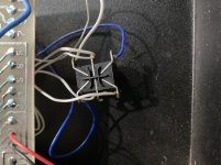
I am modifying a friends Big Muff Pi, Russian version 8 and the wires are so frail that the LED broke off from the main circuit board. I am trying to find where they connect. Where I have them now the LED just lights up always. Any help would be appreciated.

Like this one:

1663205796897.png
 
It has been a long time since I saw the inside of one of these in person.... a long time.

It looks to me like maybe this wire should go to an offboard current limiting resistor, to the LED anode, then LED cathode to the footswitch.

1663208987082.png
 
Here’s the footswitch

Let me know if you need me to trace a wire…
 

Attachments

  • A69036CA-BC01-4035-84F7-82DFD50499DA.jpeg
    A69036CA-BC01-4035-84F7-82DFD50499DA.jpeg
    296.3 KB · Views: 13
It shouldn't be too hard. Just look for the подключение светодиода and then just впаять туда светодиод. I guess you could размягчить проволоку водкой or переделывать все это дело. It's up to you. Doesn't sound too tricky to me.
 
There may be some useful info here but I bet I didn't get detailed enough ...

I do remember selling this and buying the ehx green reissue and a rat2 from sweetwater with the proceeds, then modding both of those. I still have them both and they're amazing. I'd like to get a set of the smaller sovtek knobs for the muff but can't justify spending almost $30 on knobs
 
Last edited:
This version already has a 3pdt foot switch, it looks stock. I think they used silk for wiring never seen anything this fragile. Lol.

I am going to look back at it again tonight, I should have taken some pics but some stuff came up. It does sound great, just need to get the LED working.

В Советской России вас освещает светодиод.
 
yeah I assume the dpdt switch in the one I posted links to was part of some ham-fisted unsuccessful repair work as I bought it in non-working condition. It doesn't match the original or any sovtek I've had my hands on.
 
I'm trying to wrap my head around this schematic.... particularly the LED / bypass wiring.

The way this is drawn the LED would be lit (and brightness controlled by the volume pot) when the effect is in bypass.

Am I missing something? I'm assuming the throw is drawn on the wrong node, and should actually be on the point that goes to ground.


1663252785633.png
 
Last edited by a moderator:
Looks wrong to me as well. It doesn’t make sense to have to LED go to output in bypass. Definitely think the node should be on the ground point.

EDIT: Is it wired like that on all of the Kit Rae schematics?
 
Last edited:
  • Like
Reactions: fig
the LED switch in that schematic is incorrect. In bypass the LED goes to effect out and doesn't reach ground to complete the circuit ... also I don't believe they ground the circuit input while in bypass.
 
Last edited:
So here is what I got, finally took some pics.

Trying to figure out where this wire should go on the footswitch?

1663288376447.png


And some wires broke off the footswitch itself.

1663288626947.png
 
That first wire looks like ground
I bet it goes to the top middle lug…
 
Last edited:
  • Like
Reactions: fig
I have a black muff like that. I never play the thing anymore because the whole thing seems fragile. Got it new back in the late 90s. Everything but the led still works fine. I don’t think mine has a 3pdt stomp but I’ll take a look when I get a chance.
 
So the wires are so brittle I am going to have to rewire the foot switch. Some of the footswitch wiring is going to the center lugs of the volume and sustain pots. Is this for ground? These are 100k pots would they be A or B pots?
 
Also here is the back side of the PCB.

1663433024348.png

It looks like a trace was cut to the input jack. I am guessing the pink wire goes to the LED since it was battery powered by OEM?
 
Back
Top