mybud
Well-known member
Health warning, long and wordy post ahead:
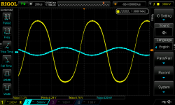
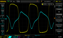
Ok, so I've been revisiting/fixing/housing half-completed builds as 2023 unfolds. I had Veroboarded this singing and dancing all-FET version of the Zender Blackface preamp awhile back (http://redcircuits.com/Page120.htm). But it was decidedly underwhelming with my original substitute 5458s for the 3819s as specified. I revisited it to check whether there was some error in my wiring and heard faint signal if I turned my trusty audio interface up to stun. I surmised that the 5458s weren't getting the right voltage, so tried a quartet of 5457s on a hunch. Gosh darn, it started singing a tune reminiscent of the old Zender Spaceman.
Since I have a small handful of 5457s and more J201s, I tried them (J201s) instead and couldn't hear too much difference. The original circuit calls for 18V, so I used two 9V batteries in series in the testing phase. Then I remembered that I had ordered some of Brian's nifty Road Rage boards...
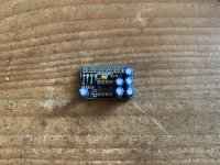
These marvellous little chaps do two versions of 9V (regulated and not), 15 and 18V, and even -9V for the Fuzz Face aficionados out there. In testing with the superbright green LED I had in mind, it was blindingly bright. I thought of running the LED off the regulated 9V option and the main board off 18V to mitigate the brightness a bit.
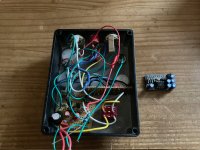
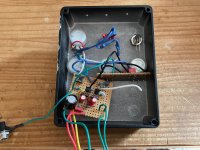
Here you see this morning's status quo (in progress). After some tweaking, splicing wires, removing a solder bridge (who me?) and other corrective measures, I finally boxed the whole mess into a 1590BB whose drilling I had earlier borked good and proper. I'll spare you the final gut shot, which is not pretty.
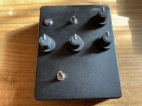
In short, I love this thing beyond words. Four JFETs, a couple of resistors and caps, four pots, simple but effective in capturing the Zender Spaceman sound. I especially like the low end and glassy brite switch (you can almost smell the antique Tolex), but there are wealth of toans in there for the patient experimenter and plenty of nice fuzzy goodness for the distortion lovers. I find the whole counter-intuitive (at least to me) aspect of JFETs endlessly fascinating and would love to try getting this to work with 5458s or 5459s. I'll breadboard another in due course and see if mycalculations hunches for modding the input stage for these alternatives are in or near the ballpark.
Thanks, as always, for reading. Now go Veroboard something...
Ok, so I've been revisiting/fixing/housing half-completed builds as 2023 unfolds. I had Veroboarded this singing and dancing all-FET version of the Zender Blackface preamp awhile back (http://redcircuits.com/Page120.htm). But it was decidedly underwhelming with my original substitute 5458s for the 3819s as specified. I revisited it to check whether there was some error in my wiring and heard faint signal if I turned my trusty audio interface up to stun. I surmised that the 5458s weren't getting the right voltage, so tried a quartet of 5457s on a hunch. Gosh darn, it started singing a tune reminiscent of the old Zender Spaceman.

Since I have a small handful of 5457s and more J201s, I tried them (J201s) instead and couldn't hear too much difference. The original circuit calls for 18V, so I used two 9V batteries in series in the testing phase. Then I remembered that I had ordered some of Brian's nifty Road Rage boards...

These marvellous little chaps do two versions of 9V (regulated and not), 15 and 18V, and even -9V for the Fuzz Face aficionados out there. In testing with the superbright green LED I had in mind, it was blindingly bright. I thought of running the LED off the regulated 9V option and the main board off 18V to mitigate the brightness a bit.

Here you see this morning's status quo (in progress). After some tweaking, splicing wires, removing a solder bridge (who me?) and other corrective measures, I finally boxed the whole mess into a 1590BB whose drilling I had earlier borked good and proper. I'll spare you the final gut shot, which is not pretty.

In short, I love this thing beyond words. Four JFETs, a couple of resistors and caps, four pots, simple but effective in capturing the Zender Spaceman sound. I especially like the low end and glassy brite switch (you can almost smell the antique Tolex), but there are wealth of toans in there for the patient experimenter and plenty of nice fuzzy goodness for the distortion lovers. I find the whole counter-intuitive (at least to me) aspect of JFETs endlessly fascinating and would love to try getting this to work with 5458s or 5459s. I'll breadboard another in due course and see if my
Thanks, as always, for reading. Now go Veroboard something...


