BurntFingers
Well-known member
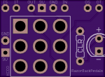
I have some of these:

I'd like to use them on some projects but as you can see there designed for the DC jack to be side mounted by the switch. My boards have the 9v at the top of the pedal PCB where the DC jack lives, like pedalpcb designs.
So... How to use both together? Run a wire from 9v jack, to the switch board, then back to the pedal PCB? In to the board at the usual spot up top, then another wire to jump from there to the switch?
I guess I don't have to use them but I'd like to get them used for something.


