Buddy's Breadboard and Circuit Design Notes

BuddytheReow

Breadboard Baker
Hey all,

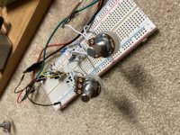
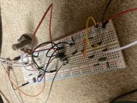
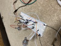
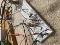
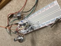
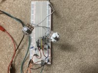
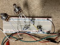
If you are frequent travelers of this forum you may have noticed that I've been asking a lot of breadboard questions recently. What kind of breadboard is best? How do I mount pots to them? Jumper cables? I finally bit the bullet and did a Tayda run. As of today it is still in transit. However, I realized I was trying to get rid of an Arduino starter recently (BTW still up for grabs so please message me; it is barely used) and it had a breadboard and some jumper wires in it so I decided to take it out and start!

A little background on my building/electronics...I started building toward the end of 2019. My wife just finished reading Adam Savage's (the Mythbuster's guy) autobiography and told me I would probably like it too since we were both fans of the show back in its heyday. At one point in the book there is a picture of him in his apartment kneeled on the floor over a telecaster with all it parts strewn all over the floor. He talked about just wanting to learn how things work by tinkering. Now, I've been playing guitar for almost 20 years (took almost 5 years off due to grad school and CPA exams - I am an accountant and yes, I breathe Excel :)). I thought to myself after seeing that picture: "Hey, this guy has no clue about how a guitar works, but I do from a high level. Maybe I should give it a try and build a guitar." So I bought a kit which included sanding, finishing, and wiring the pickups/pots. At first I was nervous about the soldering part since I've never done something like that before. Thank you YouTube and my dad for helping out on that! Soldering was pretty simple, and THAT's what sparked the "creator" in me. From there, I decided to build a tubescreamer kit from General Guitar Gadgets. From there I stumbled upon this site and also discovered Tayda. I told myself and my wife "I can save A LOT of money building these myself!" :rolleyes: 4 pedals later I decided to go down the stripboard path; again, I thought I was "saving" even more money vs buying PCBs but realized quickly the tradeoff of tidiness. Stripboard builds then required me to build a test box to essentially bypass the offboard wiring step to see if a build works and am super grateful for it. IMO, the more complex the circuit the more likely a PedalPCB purchase is necessary due to board size and again, tidiness.

So....maybe 3 dozen stripboard builds and 4 pedals later, I started getting tired of building clones. Don't get me wrong, I learned a TON about circuits mostly due to troubleshooting and learning how to do that process myself mostly due to you guys and the rest of the internet. Sure, clones are nice to have, but I wanted to take the "create" process a step further and build a circuit from scratch. My only formal education was high school physics where we spent a month or two on electricity. That was 15 years ago (showing my age here) and remember virtually nothing other than ohm's law and the right hand rule (electomagnetism). Building from scratch is a tall order if you have no idea how things work.

Getting the bug to create forced me to learn a lot of the basics in circuit design and I'm still learning here. The learning process started with the basics (this is what a resistor/capacitor/diode/transistor/etc. does) and am now learning some basic pieces (basic booster, diode clipping, tone stacks, etc.). I will be sharing my builds and any notes here for anyone who wishes to go along the journey with me. First build coming soon...
 
The first thing I took to my breadboard was an LPB-1. Made one mistake and the signal did not get louder, but it did conduct signal. The issue was that I attached the output cap to the base rather than the collector. Simple fix and lo and behold, it worked!
Decided not to take pics of this for one reason, but justified it into 2: the circuit is not that exciting and I didn’t think of taking pictures until I took all the components out!

Another thing I noticed is that if keep breadboarding with the same components, particularly resistors, the leads will snap off. Not sure if all resistors are like this or if that’s the way Tayda makes their products. So, I decided to bite the bullet and drop $10 on Amazon for a basic resistor kit specifically for breadboarding. This way I can still build on the side with my main components and not have to worry about breaking the leads off of them.

I will share my first “real” build here shortly…
 
OK. I've been spending the past few days on Jack Orman's site (muzique.com). Big shout out to one of the original gurus. Anyways I stumbled upon this as a starting point. It is taken from a Big Muff. Taking the diodes and C3 out, it is a simple booster. The issue I have is that my pickups are a bit too hot for this circuit since they are humbuckers, although my LP has a coil splitter. This makes the transistor gate slightly and sounds a bit like a fuzz. Correction, I believe the term here is clipping. One note here is that I used a 180 ohm resistor instead of a 150 for r4. Doesn’t that affect the gain? Need to look at my notes.
1627583954299.png

From here I experimented with the diode section and used the standard 1n4148. I didn't like the "soft clipping" here since the guitar is clipping it slightly already. So, I moved the diodes after C2 and shunt to ground to get a hard clipping sound and removed C3 entirely. Muuuuuch better!

Continuing to dig around the site I decided to add a standard BMP tone stack after the clipping. The internet says this is a passive tone control and now I know why...this sucks out a decent amount of volume. From the tone stack goes the 100k volume pot to ground.

Pics to follow
 
Last edited:
Since these are mostly Big Muff circuit blocks, I have decided to call this the “Egg McMuffin.”

Edit: Soundwise it is decent, but I know I can start playing with the EQ filters a bit to get something better. The tonestack made a HUGE difference in the tones generated. Perhaps I should tack on a recovery boost stage afterwards instead of almost unity? Maybe another day..
 

Attachments

  • 029AB726-4FA1-4F8C-AE55-C9E832EB4EA6.jpeg
    029AB726-4FA1-4F8C-AE55-C9E832EB4EA6.jpeg
    133.7 KB · Views: 24
  • 6A9EFAE6-C211-41EF-BFA2-6DBB3AA0139B.jpeg
    6A9EFAE6-C211-41EF-BFA2-6DBB3AA0139B.jpeg
    141.7 KB · Views: 25
  • 151C12DD-0217-4B3D-9088-9E1BCEFEDCBA.jpeg
    151C12DD-0217-4B3D-9088-9E1BCEFEDCBA.jpeg
    137.8 KB · Views: 23
I’m still going through basics here, but now I’m trying to mix and match circuit blocks. This is an Electra distortion with 4148 diodes into a BMP tone stack followed by a BMP recovery stage. Curious, couldn’t I just put another Electra distortion after the tone stack and remove the diodes? I mean, that would make it a booster, but still…

soundwise it’s a little boring but the tone stack helps. I can definitely tell from the sound that I’m using transistors due to hot pickups. I’m going to see if I can take a stab at an opamp circuit.

I call it the “Electric Muff”.
 

Attachments

  • 5E9AEFD5-44E4-406D-A0CA-93EBE449EE7E.jpeg
    5E9AEFD5-44E4-406D-A0CA-93EBE449EE7E.jpeg
    157.2 KB · Views: 10
  • 8910725B-A0B0-48E8-8496-E3FF62A42D89.jpeg
    8910725B-A0B0-48E8-8496-E3FF62A42D89.jpeg
    145.5 KB · Views: 11
  • 13C8D6CF-3783-4279-B75D-0D2B08631611.jpeg
    13C8D6CF-3783-4279-B75D-0D2B08631611.jpeg
    150.5 KB · Views: 10
  • Like
Reactions: fig
This is the first "building block" I learned to me makes the most difference to the sound of nearly any circuit. It is a Big Muff tone stack and is considered "passive", meaning it doesn't take any power to use and there are a few components to ground. The downside to this simple circuit is that it drops the output volume enough to be annoying. At least in the BMP circuit this is done after all the other clipping stages before the boost/recovery section. If anyone is interested in learning more about this check out Jack Orman's site here http://www.muzique.com/lab/atone.htm.

1627651022398.png
 
This is the first "building block" I learned to me makes the most difference to the sound of nearly any circuit. It is a Big Muff tone stack and is considered "passive", meaning it doesn't take any power to use and there are a few components to ground. The downside to this simple circuit is that it drops the output volume enough to be annoying. At least in the BMP circuit this is done after all the other clipping stages before the boost/recovery section. If anyone is interested in learning more about this check out Jack Orman's site here http://www.muzique.com/lab/atone.htm.

View attachment 14263
This is helpful. I breadboarded a Axis Fuzz this morning, and it was so bright that it just about blew my ears off. I may tack this on to the end of the circuit and see what happens…
 
  • Like
Reactions: fig
This is helpful. I breadboarded a Axis Fuzz this morning, and it was so bright that it just about blew my ears off. I may tack this on to the end of the circuit and see what happens…
I would be careful here. If you find that it's too bright to begin with then half of the tone stack pot would make it worse. I would use the top half of this circuit here but remove R1. This is taken from that same article I shared.

1627666083742.png
 
CRAP!

I typed a lot in a reply to the topic and was switching between windows to grab some URLs for you, then accidentally wiped out everything I'd written trying to click back on this thread and closing the window instead. GRRRR 😾


Trying to recap from memory (at least it'll be more brief this time round)...

Enjoying living vicariously through your efforts here, thanks for posting.

Most EQ is "lossy", 'cause most EQ is just dumping frequencies to ground — hence the need for a recovery stage (or mega-boosted before the EQ). By all means, try the Electra sans diodes as a recovery stage. Try a SHO, too, then try an MXR Micro-amp as your op-amp recovery stage...

Check out Brian Wampler's "How to Design Circuits" or "How to Design Pedals" or whatever the title actually is — there're PDFs of it floating on the Interwebs or you can buy it on glut-online-seller Ahmalgazone.

Also check out ESP for "Designing With Opamps" Parts 1 & 2 by Rod Elliott.


@Coda Check out AMZ's take(s) on Mark Hammer's Stupidly Wonderful Tone Control (SWTC). Just the thing for axing the edge off your Axis.

Sorry guys, not going to give you the URLs, lest I inadvertently delete my post yet again — I'm sure you can seek out the suggestions if you like.
Thanks for the tip. I looked into, and added it to my breadboard. I can definitely hear a difference in tone, but the tone is still pretty piercing. I think that's the nature of the pedal. It was based on the Fuzz-Rite, and that pedal also seems to have too much treble. I say "seems" because I only hear it live in the room. Recorded you'd never know. Meanwhile, my ears are hear bleeding...
 
@Mcknib pointed me toward Beavis Audio. I was drawn to the breadboard projects since that's what im into right now and loving the learning process. One of the things I stumbled upon comes from here. http://beavisaudio.com/beavisboard/projects/bbp_DiodeMods.pdf. I'm going to be doing some projects from here since there are a dozen or so relatively easy ones. I won't match the breadboard layout because I kind of want to figure those things out on my own.

Personally, I don't agree with the asymmetric clipping ones since one lead of the single diode isn't connected to anything. The simple fix is to extend the lead to match the double diode connection. Since in my head the layout doesn't make sense I didn't try it as written.

I think this is a great resource right here for anyone who's interesting in designing or modding a distortion/OD/fuzz pedal. In my opinion the 2 warp controls are very subtle. Either that or the pots I used were the wrong value. I think I used 100k.

I'm a distortion junkie, so naturally I tested with LEDs. Looking at any voltage drop chart, Red ones clip the most and white clips the least. To remember I was reminded of how kids learn the colors of the rainbow: ROY. G. BIV and in that order from most to least clippping.

1627912574644.png
1627912188117.png
 
For anyone who's been reading this thread or cares, anything that I post with either a screenshot or link comes from someone else who did all the work and I do not take any credit for their time an effort. I am merely collecting and passing along any information I find that may be useful to myself or anyone else who wants to join me in the learning process of circuits.

Sorry. Part of me felt like I had to put a disclaimer in at some point :p
 
Before I went away over the weekend I took some time and looked through the Beavis Audio projects for a good modding project. I think modding an existing circuit would allow me to understand what part does what in any given circuit. As mentioned I am a distortion junkie so I wanted to start with a classic: MRX Distortion +.

As I'm writing this I realized this is something that Chuck does on a frequent basis, but I wanted to share my experience and also look at his posts too to cross reference.

I have built this circuit on stripboard before and was pretty pleased with the overall sound given the amount of parts it takes. Now that I have a breadboard its time to "tinker" as my wife likes to say.

Since this is a basic, hard clipping circuit I decided to tweak the clipping using some of the mods listed above. Too the diodes out first to test the raw opamp sound and it was pretty clipped to begin with. Swapped the 1n914 with red LEDs and loved the "harsher" sound it gave. My first mod!! I then tried the "warp" mod and found it too subtle for my taste. Asymmetrical LEDs made the sound a bit "warmer" but still the desired harshness, so I kept it in.

I looked at the power supply and saw it was a very basic voltage divider with a 1uf DC filter so no changes would be made there. Does anyone know the purpose of R3 (1m)? Something to do with impedance maybe? Still having trouble with this in relation to circuit design.

I then took a look at the negative feedback loop. Taking the 10p cap out made the sound too harsh, but the larger the values I subbed in there removed more overall distortion. Decided to keep the cap at 10p. R6 I found out controls the overall gain of the opamp, so I put in a 2.2m and kept it. C4 and R5 to me appear to be a tone filter and didn't get around to playing with it since I am not that educated in that yet.

In/out caps (c2 and c6). C2 provides DC and tone filtering? The larger the value of c2 i used the more bass came through. I kept it at 1u since i think it should have more "chunk". C6 looking at this after the fact seems to be a low pass filer, but could be wrong. Anyway, the larger values I put in there the less overall distortion I heard. Taking the cap out entirely didn't change much of the sound.

The original IC is an LM 741, but I went with what Beavis Audio has in the project. I tried swapping that out for a tl072 and noticed no difference in sound to my ears.

Any ideas or other good mods to do for this? Was thinking a tone control, but since I only know BMP and given how bright the sound already is and the volume drop it produces I decided to nix it. Maybe when I learn active tone stacks I can circle back to this project.

Edit: pics added

1627916696202.png
 

Attachments

  • 6AC5A154-66E8-4FE0-8E7B-4E0059AB68C4.jpeg
    6AC5A154-66E8-4FE0-8E7B-4E0059AB68C4.jpeg
    101.1 KB · Views: 14
  • 86958027-B91B-4762-BCA7-A46279F5B92E.jpeg
    86958027-B91B-4762-BCA7-A46279F5B92E.jpeg
    122.5 KB · Views: 13
I might be mistaken here, but R1 is the pull-down resistor to lower input impedance, and the voltage divider is R2/R3.
 
I thought the pull down resistor is right after the signal input and goes to ground. There doesn't appear to be one here
 
  • Like
Reactions: fig
Yeah, you're right! Could it be an attenuation setup for when it dovetails into the audio and opamp?

One way to know for certain what effect it has is to audio probe / or grab a waveform at pin 3 of the opmap.
 
Last edited:
For anyone who wants to learn with me...

When I started this thread I had the goal of being able to design my own circuit. As a distortion junkie, I really wanted to build an op amp based circuit with tone controls, diode selectors, boosters, etc and move on from there to different effects. Here's my first breakthrough after doing a lot of reading and breadboarding. It is a basic, non-inverted op amp gain circuit and the design is seen in things like the Dist +, Rat, Guvnor, etc.

I found this on General Guitar Gadgets and will post the link here. This goes through a lot of the parts to build a basic clipping circuit with tone control. I stripped it down to, what I think, are the bare bones. The power supply stage is removed here, but it is a simple voltage divider along with a 4.7uf electrolytic cap to filter and ripples and highlighted which voltage goes where. Also, the IC needs to be grounded. A 4558 IC is at pin 4 for ground and pin 8 for 9v. I will explain what each part does and directly comes from the circuit analysis from the link. My comments are in green.
1628011607075.png

R1 acts as a click-preventing resistor. It cuts out all clicks and other unpleasant sounds from the signal. This part is needed or else the circuit won't work.
C2 also filters DC voltage from getting into your guitar. R1 and C2 also form a high-pass filter. Cuts frequencies below 16hz.
R2 and C1 form a low-pass filter, which rolls off out the radio frequencies. About 16kHz. Between these two filters only guitar signal can go through to get amplified.
Input gets biased through R3. Still scratching my head why this is needed but I tried removing it here and the circuit didn't work. So, it stays. Brian Wampler likes to use 470k here for most of his circuits.
R4 and R5 set the gain. Since R4 is a potentiometer, the gain can vary from 1 to 101. I think the calculation is (R4 + R5)/R4. Higher pot values mean more gain. Lugs 2 and 3 are connected.
R5 and C4 form another low pass filter. I didn't think this was necessary since it is merely a filter, but the circuit wouldn't work as it should. This combo determines the frequency that gets passed on to be amplified as per Brian Wampler (went through his "advanced" book last night) and was my Eureka! moment.
R4 and C3 form the high pass filter, and since R4 is a pot, the roll-off frequency will vary as you turn the pot.
C5 prevents DC voltage from getting into your amp. Since C5 and the volume control R7 form a high pass filter, the value of C5 has to be high enough to prevent the roll-off frequency to interfering with your signal (10uF should be enough). I think I put a 100n cap here since that seems to be the standard in a lot of diy circuits. Sound was a bit treble-y, but I like that where you can hear the pick attack.
R7 is the volume control.
 

Attachments

  • FC8036CB-EAB2-4A48-AE2C-B56BE1F84416.jpeg
    FC8036CB-EAB2-4A48-AE2C-B56BE1F84416.jpeg
    132.7 KB · Views: 3
  • 62294763-95BA-4114-9AF0-A840EE3FFF44.jpeg
    62294763-95BA-4114-9AF0-A840EE3FFF44.jpeg
    147.6 KB · Views: 3
Last edited:
In writing my last post and trying to find frequencies of guitar signal I stumbled upon this. Seemed very useful and comes from here.

Key Audible Electric Guitar Range = c80 Hz - c7,000 Hz

(These are the frequencies most people can hear, most everything else is texture and atmosphere.)

  • 20 - 80 Hz : Deep Bass, can add muffle and muddiness, can also thicken sound to a degree. 20 Hz usually lower kick-drum frequency, low-end bass is around 60 - 100 hz. For electric guitar you would typically cut anything below 100Hz
  • 80 - 120 Hz : typical low-end guitar frequencies - cut below 100hz to give space to low-end bass and percussion
  • 100 - 300 Hz : used to add fullness of sound / thickness & body to guitar, just a little though as too much here muffles and can create flubbiness / warble
  • 300 - 1,000 Hz : Liveliness / attack - adds some electrical sizzle
  • 1,000 - 2,000 Hz : ’Honk’ / nasally guitar sounds - boost or cut
  • 2,000 - 2,500 Hz : classic mid hump or scoop
  • 2,500 - 3,000 Hz : boosting here gives you more snap / pick attack
  • 3,000 - 7,000 Hz : Brilliance and Presence / Sparkle
  • 7,000 - 11,000 Hz : Treble boost to accentuate distortion
  • 10,000 - 20,000 Hz : sort of very high end textural fizz or ’Air’ - pretty much inaudible to most
 
Forgot all about the tone control @BuddytheReow heres a very tiny one

The guy that sent me this @Darrencp tried it with an erupter fuzz said it sounded good I haven't tried it yet BTW should be easy enough to draw a schematic and try it on the breadboard

tinytone.jpg
 
  • Like
Reactions: fig
R1 acts as a click-preventing resistor. It cuts out all clicks and other unpleasant sounds from the signal. This part is needed or else the circuit won't work.
The pull-down resistor isn't necessary and the circuit will still work without it. Were you unable to pass signal if you removed it?

Input gets biased through R3. Still scratching my head why this is needed but I tried removing it here and the circuit didn't work. So, it stays. Brian Wampler likes to use 470k here for most of his circuits.
You're right that the this sets the bias for the op amp so the virtual ground is 1/2(supply voltage) (i.e., Vref). The resistor provides a path from the buffered voltage divider reference to set the bias of the op amp. This is an AC-coupled circuit, so the bias has be be supplied. R3 is a load that provides a DC return path for Vref and sets the AC impedance.

Here are some resources you might find helpful:
https://www.renesas.com/us/en/document/apn/how-bias-op-amps-correctly?language=en
(See section 3 for the R3 question and why C4 is required.)
 
  • Like
Reactions: fig
Back
Top