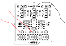
Calamity Fuzz and Biasing j201 Mystery

Hey gang,

I'm troubleshooting a Calamity Fuzz build. Wasn't crazy hard to populate but I'm in need of some help.

LED turns on, Works when bypassed, but no effect. I can hear hiss and different frequency range changes when I flip the 3 toggle switches, so that must be a good sign.

I tested each component pre-populated so it can't be that. This is the first build I've needed to use a 5v1 zenner diode, and i used an NTE5010A.

I've read on a couple other posts about biasing the J201's and making sure the drain resistors are proper value. These posts specifically discuss the PedalPCB SOT23 adapter but I used thru hole j201's via Tayda.

Can anyone walk me through or send me some info on how to do this? I'm pretty frustrated. I'm def going to start using those adapters from now on.

Anyway, thanks a ton and much love. 0.jpg
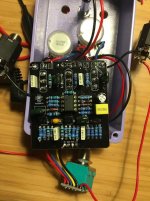
 
Hi!

What revision is this board? It does not match the current build doc.
Also, what value resistor did you make in series (teepee on bottom left of pic)?
 
I've experienced a similar problem on my build: I suspected bad J201's at first, swapped em out with the SMD variants, and still...nope.

I mean...it was a little better. I could at least get the gate to open. But...I still had bias issues. The SMDs still have a bit of variation to them.

It's a build that is deceptively advanced. R4 and R6 are the resistors to look at...

The great Chuck Bones recommends a Vd of 4vdc for Q1 and a Vd of 0.5vdc at Q2. That's a (V)oltage measurement between the (d)rain pin and ground.

Sockets and a trimmit would help here. Pop the trimmit in the socket, adjust till you reach the desired Vd, then pull the trimmit, measure the resistance across the trimmit, and replace with a resistor of similar value.
 
Hi!

What revision is this board? It does not match the current build doc.
Also, what value resistor did you make in series (teepee on bottom left of pic)?
Wow,

I did not even realize that lol. I JUST ordered it and used the build docs that are on the website. Where would I find build docs for previous versions?
 
Wow,

I did not even realize that lol. I JUST ordered it and used the build docs that are on the website. Where would I find build docs for previous versions?
Well, at least the image of the silkscreen is different. Whether or not the circuit itself or any values have changed I don't know. You may want to pose that question on the Missing Build Docs forum just to have the matching one.
 
It doesn't look like the circuit itself changed—just the layout. @Stickman393 is right: The JFETs have to be properly biased for this circuit to work. Do you have a multimeter and do you know how to use it? The resistors that may need to be adjusted are R4 and R6 in the current schematic. Can you provide the current voltages that you're getting?
 
  • Like
Reactions: fig
Well, at least the image of the silkscreen is different. Whether or not the circuit itself or any values have changed I don't know. You may want to pose that question on the Missing Build Docs forum just to have the matching one.
Ok yea, I double checked and the values on my build match up so I am good there.

I do have a multi meter and I'm pretty familiar with testing caps, resistors, diodes, etc.

The real question is, how do I check the voltages for the j201's? I think this is where I need to real help. I haven't used a multimeter to do this before.

Also, thanks everybody for the help, I sincerely appreciate it.
 
Connect multimeter probes as below - black wire to the negative supply (GND) and red wire to marked pins of the Q1 and Q2.

1627569426234.png

Also - you can replace (temporarily) Q1 and Q2 drain resistors with trimmers. Set proper voltage, measure trimmer resistance and replace with closest value resistor.
But one thing on a schematic puzzles me - Q2 source resistor value. With 33k drain resistor, 680R is quite low in value (from my experience). I'm just looking at ltspice simulation of the part of the schematic. Q1 - 16k and 1k - ok. With average MMBFJ201 Q1 should bias around 4.5V. Q2 - 33k and 680R - this combination gives around 400mV on Q2 drain.. replace 680R with 6k8 - 4.5V... if you want to keep 680R source resistor and bias Q2 @ 4.5V than you should lower value of the drain resistor to 10-12k (depending on the transistor used).
Unless I'm all wrong here... :)
Maybe @Chuck D. Bones can help here...

edit.
I cannot rule out that such odd Q2 biasing is intended, and that's what makes "fuzz" here. If yes, than you should ignore my comments about adjusting Q2 resistors.
 
Last edited:
You need J201s with very low Idss. They have to be hand-selected. The usual problem with the Calamity is the drain voltage is way too low. I suspect your J201s are fugazi. When did you buy thru-hole J201's from Tayda? They've been out of stock for ages.
 
You need J201s with very low Idss. They have to be hand-selected. The usual problem with the Calamity is the drain voltage is way too low. I suspect your J201s are fugazi. When did you buy thru-hole J201's from Tayda? They've been out of stock for ages.
I bought them a month or two ago? I bit the bullet and ordered the surface mount J201's off Tayda and the adapter+trimmers from pedalpcb. I'm going to switch out the old ones for the surface mount and see if I have more luck.
 
Back
Top