Calamity Fuzz build

MattHolmes

New member
Hi everyone, first post here so please forgive me if I get anything wrong!

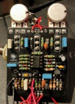
I have been building the Calamity Fuzz PCB over the last few days and ran into an issue other people seem to have had in the past. Essentially the problem is that in bypass I'm getting a signal but when I engage the foot switch the LED comes on, there is a 'noise' from the pedal like a faint static and playing with the switches elicits some pops but there is no other noise.

Checking the forums I found out about biasing the J201s which I tried to do, but when I checked the voltage on both drain pins I was getting around 8.2v on each which is a far cry away from the Q1 4v and Q2 400 mV. Checking the voltage on IC1 pin 1 I'm getting around 3.7v which seems very high.

I attempted to bias Q1 and Q2 down to their correct voltages but the only way I could manage it was by getting into the Mohm range for both which told me something was way, way off!

Could anyone recommend anything else I could try? And I apologize now for the quality of my soldering on the board and wiring!

Thanks!

Edit: the two pairs of wires trailing out from the bottom of the board are going to a breadboard with pots on it which I was using to try and correctly bias the j201s
 

Attachments

  • IMG_20210802_235021.jpg
    IMG_20210802_235021.jpg
    1.6 MB · Views: 40
I sourced them from eBay so I have no idea how legitimate they are.

I have ordered some replacement SMT J201s from a different website. I'll try them out and report back
 
Last edited:
8.2v on each? 😲

What's your supply voltage, if you don't mind me asking?

If you're at 9V, then that means that you're only seeing a .8v drop across R4 and R6. Which means that you have a LOT of resistance between your drain and ground. It's no wonder you're having to dive into the megaohms there.

Something isn't right: either the J201s, or a few bad solder joints.
 
Last edited:
My first thought was a bad solder joint somewhere, I have reflowed all the solder joints and cleaned the board but the problem is still much the same.

Supply voltage is around 9.1v, I'm using an old multi pedal power supply for testing. I have measured the power supply at the point it enters the board and can confirm it is 9.1v.

I have some replacement SMT J201 JFETs being delivered today hopefully. I plan on switching them out this evening and providing an update. This is the first time I've come across an issue like this and it's made me concerned about some parts I have on order for a Low Tide build that are also from eBay / China!
 
If you don't know what to look for with JFETs and how to measure/sort them, I would advise against buying from ebay and stick to verified sources. The extra cost will hopefully be offset by the lack of headaches with builds.
 
If you don't know what to look for with JFETs and how to measure/sort them, I would advise against buying from ebay and stick to verified sources. The extra cost will hopefully be offset by the lack of headaches with builds.
I tend to stay away from eBay for precisely this reason, but my local supplier (Farnells in the UK) didn't have stock of the J201s and I had to improvise. I know that Mouser stocks the SMT version and in future I will make sure I order from them.
 
Update as promised, the main problem was indeed the "j201"s or whatever they actually are, swapped out for the SMT board versions and now I'm getting some response from the board. I'm still having a problem getting the pedal to perform though, when I put it in the enclosure I started getting a shorting issue which I assume is related to the DC connectors I have with a metal collar on them. At least I'm one step closer now!
 
That's great to hear! And yeah, I seems as if you have the DC jack that will short the sleeve to the enclosure. Since the ground is connected to the enclosure through the phone jacks, you'd be shorting the power out. Do you have any of the boss-style plastic DC jacks?
 
I've just ordered one which should hopefully show up in a couple of days so I'm shelving the pedal until then. I've got to say that I was not expecting the build to be nearly as difficult as it has been, between the J201 problems, biasing the new JFETs and now the grouding problem this pedal has been a real test! I'm usually pretty good with DIY builds and have plenty of successes but for some reason I never seem to have any success with guitar pedals.
 
Also, I have noticed that the volume has dropped considerably since putting the board in the enclosure. Any advice for what to try? And thank you everyone for your help and support so far, it's very much appreciated!
 
You didn’t pick an easy circuit to start with! Did you get the bias correct for the two JFETs? You definitely have a grounding issue, so that could cause the volume drop. This is a very loud circuit, so that’s definitely an issue. Confirm the values and double check your IC voltages outside of the box (until you get a suitable DC jack).
 
Even real J201s have to be hand-selected for Idss in the Calamity. Benny was right, this is a tough build even for an experienced pedal builder. Check the other troubleshooting threads for the Calamity for guidance on how to select the JFETs.
 
I think I have the bias correct, although I have had a lot of trouble selecting resistors for the drain on Q1 and Q2. I've opted to switch to trim pots so I can easily dial in the bias rather than trying to daisy chain resistors and making a mess of the board. I probably won't get much chance to work on the board now until Sunday but I'll make sure I keep updating this thread with my progress in case anyone else comes across the same issues.

At this point, I'm starting to wish I'd just built a Big Muff instead 😂
 
Don't feel bad: I ripped up my board pretty badly going through my first calamity build. Had no idea about the aforementioned hand-selection of jfets. I got it pretty close on my first build after replacing my J201's with SMD versions and tweaking the bias...but the results were aesthetically...bleh.

I built a simple Vero JFET tester for my next calamity build...details are in the build reports sub forum: I'll be doing that one with some pre-tested J201s.
 
Quick update on the build, I replaced the DC jack with a plastic one at the shorting issue has been resolved. The resistors for Q1 and Q2 have been replaced by linear 50k trim pots and will most likely stay that way.

As it stands the pedal is now semi functional. The Crush and Gain switches work as does the onset control and volume, however the tone switch seems to do nothing but suck the volume and the LED seems to have stopped working. I am not really sure where to start with trouble shooting these issues, I have reflowed all the connections and cleaned the board thoroughly with IPA and a toothbrush.

Thanks again for your continued support with getting this working, any ideas on where to start with the LED and tone control would be amazing.

Also, even though it's not completely working yet the pedal sounds so good!

Edit: updated the correct switch issues
 
The LED is a simple circuit. Check that the circuit elements on the board are working properly and verify your switch.

For the mode toggles, we need to be sure we're talking about the same thing. The controls (when looking at the face of the pedal from the outside) are arranged from left to right: CRUSH, GAIN, TREBLE. The TREBLE switch has a pretty profound effect, are you talking about that switch? If that's the case, the only thing that that switch does is bring C6 into the circuit. Verify that capacitor and that it has the appropriate connections.
 
That's the CRUSH toggle. It's interactive with the GAIN switch and the ONSET knob. Can you check for continuity between the lugs of the switch to verify the switch itself? To make sure there aren't any issues with the board connections confirm that:
  • CRUSH Lug 3 connects to GAIN Lug 3 (GAIN is the center switch),
  • CRUSH Lug 2 connects to pin 5 of the TL072, and
  • CRUSH Lug 1 connects to GAIN Lug 1.


calamity crush switch.png
 
That's the CRUSH toggle. It's interactive with the GAIN switch and the ONSET knob. Can you check for continuity between the lugs of the switch to verify the switch itself? To make sure there aren't any issues with the board connections confirm that:
  • CRUSH Lug 3 connects to GAIN Lug 3 (GAIN is the center switch),
  • CRUSH Lug 2 connects to pin 5 of the TL072, and
  • CRUSH Lug 1 connects to GAIN Lug 1.


View attachment 14628
Thank you Benny, I will check this in the next few days and post another update. I have to say that out of all the DIY electronics I've built (including hand soldering an STM32 for a MI Clouds clone) this has been the one board that has given me the most trouble!
 
Back
Top