Can anyone explain this to me?

SillyOctpuss

Well-known member
Despite having built pedals for a few years now my knowledge of how a circuit works is still pretty limited. I was looking at this schematic earlier and understand all of it except the section with the transistor below. I'm getting there with ICs, clipping, filters etc but to be honest transistors in general still confuse me.

Can anyone give me a quick lesson on how this section of the circuit actually works? I understand the basics of a transistor but signal appears to be going through the transistor and also bypassing it.

1633880625184.png
 
Guess: R13 (emitter-base) is a pull-down resistor to stabilize the base.
You need some trickle of of current going through the base-emitter junction of a BJT or the transistor won't turn on. 2m2 is a super common value.

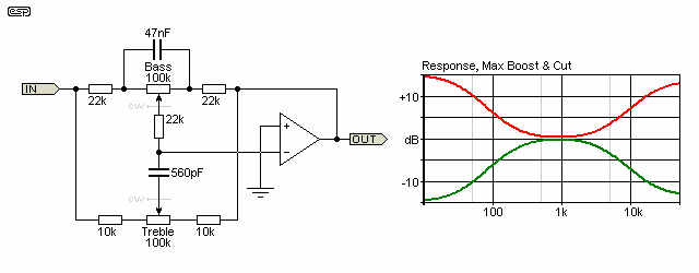
The circuit looks like an implementation of a James tone stack using a BJT transistor as the active component / amplifier.
Compare to this Brandaxall Tone stack using an opamp below, they're very similar.
dwop-f12.gif

You might notice that there is a negative feedback path connecting the inverted output back to the Treble and Bass controls. In the transistor based circuit you posted above, that path is C9. It has to be AC coupled in the transistorized version because the input and output are sitting at different DC potentials.

Also, I found @Chuck D. Bones did a writeup on James vs Brandaxall tone stacks. He understands this stuff much better than myself and the writeup probably answers most of your questions. Chucks Boneyard > Tone Stacks - Part 2 - James & Baxandall
 
So reading the link from Chuck's boneyard above this is a Baxandall tone stack and the BC549 is providing the gain. Chuck added a baxandall from the pedalpcb acid rain and apart from one cap the values are identical. Interesting stuff chaps. At least I finally understand what's going on... Mostly.
 
So reading the link from Chuck's boneyard above this is a Baxandall tone stack and the BC549 is providing the gain. Chuck added a baxandall from the pedalpcb acid rain and apart from one cap the values are identical. Interesting stuff chaps. At least I finally understand what's going on... Mostly.
Well, mostly. It's a James tonestack because there are caps rather than resistors on either side of the Treble pot.

There is also something else going on because James tonestacks can be passive, but this one has negative feedback. I think the inverted signal fed back to the Treble and Bass controls should create a more pronounced cancellation than if the pots were just tied to ground like you see in passive designs. This probably just translates to a wider sweep, but I'd need someone more expert level to confirm.
Ah ok. I called it a Baxandall because when Chuck added the tonestack from the pedalpcb Acid Rain he called it a baxandall and it's identical to the schematic I posted above except for value of 1 cap going to ground.
 
Honestly, something like this is asking me to put a booster stage in front of it and try it out on a breadboard. I’ve built the acid rain fuzz and this is pretty much the last 2 stages
 
Back
Top