CDXL Reissue Envelope Filter

Jbanks

Active member
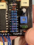
Put it together tonight and fired it up. It turns on, LED works, bypass is fine. But when on, there’s a lot of gain and distortion coming through that certain isn’t part of it. You do hear the squish of the envelope filter, but it’s heavily distorted.

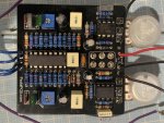
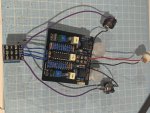
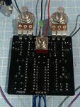
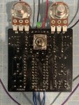
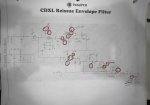
here’s a couple gut shots. Any suggestions on where to start checking would be greatly appreciated. I’ll try a audio probe tomorrow and see if that yields any clues.

thanks in advance!
James
 

Attachments

  • BB9BE5DC-BA34-4FCD-AC0A-65D2A0430B04.jpeg
    BB9BE5DC-BA34-4FCD-AC0A-65D2A0430B04.jpeg
    315.7 KB · Views: 19
  • F1DB63BE-E51B-450B-9008-60A864D8BE45.jpeg
    F1DB63BE-E51B-450B-9008-60A864D8BE45.jpeg
    331.4 KB · Views: 19
You need to post a good photo of the other side of the board as well, since that is the more likely side to show bad solder joints or possibly shorted connections. the symptoms you are describing seem to be for a wrong-value part on the board. the audio probe should be very helpful for you to isolate where the signal is getting distorted.
 
Ok here’s some back side shots of the board. I’ll start double checking the R values too.

Thanks
 

Attachments

  • DB3108B7-3069-4B6A-8AF9-F4685D56E1EE.jpeg
    DB3108B7-3069-4B6A-8AF9-F4685D56E1EE.jpeg
    307 KB · Views: 8
  • 6150A882-BBEE-4EC0-A243-9F7C138A5EB9.jpeg
    6150A882-BBEE-4EC0-A243-9F7C138A5EB9.jpeg
    328.1 KB · Views: 8
Check the value of R21. It looks like it might be 510K instead of 51K.
I checked all the values. My 22k are 22.1k Will that be affecting it? Just realized I have 22k proper now but not sure if .1k will have a negligible effect.

on to the audio probe now...
 
Ok, I did the audio probe. Attached is a diagram of the spots where the sound gets muddy. I’m not sure exactly how to follow the signal path so forgive my errors.

both trim pots seem to be losing the signal. I would either get a muddy sound or a very faint sound at best from the trimpots (leg 3 I believe ).

I also get a lot of mud out of the output for IC3 (LM13700) on the lower path. Is there a way to check if the chip is bad? I’ve never had that issue, so I usually assume user error.

If anyone has any advice on what to check form here it would be greatly appreciated. All the values for components check out. I don’t see any crazy soldering.

thanks
James
 

Attachments

  • 1261A9E0-4CEA-4D97-8593-16A96C89801D.jpeg
    1261A9E0-4CEA-4D97-8593-16A96C89801D.jpeg
    146 KB · Views: 11
Very simple suggestion (that you probs already tried out, but hey, worth chiming in?):

I just built this, too. Have you tried noodling with the trimmers and flipping the toggle into UP and DOWN mode? Depending on how the trimmers are dialed in, and especially when the toggle switch is in DOWN mode, the results can be super wild and distorted.

The UP mode is the classic auto-wah sound that I was able to dial in more quickly with the trimmers. The DOWN mode plays very differently. I tried to find a happy medium so both modes sounded fun/usable with the trimmer settings.
Yeah I definitely noticed that it got louder and more when in the down position. One trimpot clearly affects the range of the sweep. Is the other a gain pot? They’re not labeled anywhere.
 
Back
Top