Cepheid Chorus - No effect, just bypass sound, LED's working

I can't figure out what's going on and not sure what to check? I'm getting a bypassed signal, footswitch is activating the LED's, both LED's are working, the rate LED reacts to the rate pot, but I'm not getting any chorus effect? The only thing that I can do to the pedal to have it make any kind of noise is adjust the internal trim pot, either full close or full open will just make a pop sound and I'll lose signal all together. I'm using a MN3101 (I've got one from the same seller in a working delay pedal, so that chip should be good, but I did try another one just in case, no difference), a MN3007, ordered off ebay from a stateside seller so I hope it's good. Using a 1N4742 12v zener. I've got it on a socket because I wasn't sure what chips I was going to use - when I remove the diode nothing happens, still have signal passing. I soldered the jumpers on the "3007" side. Any ideas?
 

Attachments

  • IMG_2944-2.JPG
    IMG_2944-2.JPG
    623.4 KB · Views: 51
There are MANY BBD chip fakes out there. Especially on eBay. The MN3xxx series of BBDs and clocks are in short supply these days and many eBay sellers are providing fakes or bad chips. And based on the close-up view of your photo, I'd say you have fakes.

These are what real MNxxxx chips look like. All are verified working.
BBDs_July_2021.jpg

One way to do a quick test for fakes is to take a sharp Exact blade to the tops of those MNxxxx chips and see if you can flake off any of the printing. Fakes will often be sanded and re-printed or covered with a cheap coating and then re-printed. If the coating or printing flakes off, they're fakes for sure.
 
I can't figure out what's going on and not sure what to check? I'm getting a bypassed signal, footswitch is activating the LED's, both LED's are working, the rate LED reacts to the rate pot, but I'm not getting any chorus effect? The only thing that I can do to the pedal to have it make any kind of noise is adjust the internal trim pot, either full close or full open will just make a pop sound and I'll lose signal all together. I'm using a MN3101 (I've got one from the same seller in a working delay pedal, so that chip should be good, but I did try another one just in case, no difference), a MN3007, ordered off ebay from a stateside seller so I hope it's good. Using a 1N4742 12v zener. I've got it on a socket because I wasn't sure what chips I was going to use - when I remove the diode nothing happens, still have signal passing. I soldered the jumpers on the "3007" side. Any ideas?
You may be having the same issue as I had in my build, seeing as you have an MN3007 in there.

Power it up, check voltage between ground and the lead on R27 that is closer to the edge of the board. It's a 56K resistor.

If you see 0 volts, go ahead and pull the plug and check resistance between those two points: if you see 0 ohms, you have the same board that I have...and R27 bypasses SW2 and connects directly to ground.

You will need to pull that resistor and find some way to connect the lead that was formerly connected to ground to a 9v source. Given that you've soldered SW1 & 2 to configure the PCB for the MN3007, pin #1 on the BBD is the closest spot.

Go ahead and take a look at this thread for more info.


Edit: Hmmm, took a closer look, you appear to have a revision judging by the position of SW1 & 2. Looks like an extra trace under R27 on yours too. I'd check, but if you get 9ishVdc on R-27 I'd say that the more likely scenario here is that the BBD in particular is counterfeit.

Fun fact: the NTE1641 is typically cheaper, less likely to be counterfeited, and is a direct work-alike for the MN3007. The NTE1639 would be the matching clock driver, like the Mn3101. Each chip can be used interchangeably: check out my thread for an example.
 
Last edited:
It does look like a fake chip especially if you compare the M

Mine are all tested good and look exactly like @Cybercow's

I'm no expert with BBDs but you could test to see if you get signal in at pin 3, out at pins 7 and 8 and a clock pulse on pins 2 and 6 and make sure it's a dud,

Your clock driver is ok so if its all built correctly it should be putting out a clock pulse from pins 2 and 4 to MN3007 pins 2 and 6 and VGG from pin 8 MN3101 to pin 4 MN3007 as you can see in the schematic, better to check what you can to be 100% sure, it could of course be something else like the usual suspects dry joints

I don't know the voltages you should expect but as I say if your 3101 is good what you get where it connects to the 3007 should be around the same

With the clock pins afaik if one's high the other should read low


20210731_205317_copy_418x369.jpg
 
Thanks for the input everyone! I'll check these things out. Writing doesn't chip off with an exact-o, doesn't smear with alcohol either. Seemed like a fairly reputable source 200,000+ reviews, 99.7% positive. If everything else checks out - I've got some other chips coming I can swap in and test. Thanks for your help everyone! I'll keep you posted.
 
Small update - I've got it *kind of* working. I found one tiny spot on the trimpot where I can get a chorus effect - but it is pretty distorted. Is there any kind of resistor I can add along the legs to kind of limit this range and make it more sensitive? Or maybe just swap out the trimpot to a multi-turn?
 
Ehhhhhhh....there's nothing wrong with using a multi-turn. Hell, I'm doing that on my tonepad PCB version I got in the works. That said, you should get a chorusing effect from a wider range than just one small spot. Adjusting that trimpot by ear should be about dialing out the distortion...it sounds to me like there's still a problem elsewhere.

Is this still with the original Bbd and clock?

I would start looking elsewhere...I've been able to troubleshoot my builds with a cheapie scope and signal generator...but if you can fab up a audio probe from a 1uf cap and an old guitar cable, you can follow the schematic from the input through the BBD to the output and see where your signal starts to have problems.

Sometimes it's as simple as a bad solder joint. I just debugged my DC-2 clone from aion today by finding a bad solder joint and a pad that I had fudged up when I was populating the board.

It's awfully rewarding to find those little areas. IMHO. I live to fix shit.

Ic voltages would be a good reference here too, might point us in the right direction
 
Last edited:
Small update - I've got it *kind of* working. I found one tiny spot on the trimpot where I can get a chorus effect - but it is pretty distorted. Is there any kind of resistor I can add along the legs to kind of limit this range and make it more sensitive? Or maybe just swap out the trimpot to a multi-turn?
Anytime the "sweet-spot" of a single-turn trimpot is an extremely narrow range, I'll swap it out for a multi-turn
 
  • Like
Reactions: fig
I had this same problem. When I saw this thread and read about fake MN3xxx BBDs and clocks on ebay, I thought I was sunk. I had purchased 10 pair MN3207/MN3102 on ebay for just $8 😬 
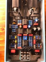
But, they looked pretty darn close to the photo @Cybercow posted, so I decided I might as well test them all.

It worked! After testing four bad sets, I found a pair that worked. Pedal sounds awesome now.

Most of the bad ones just sound like bypass, but a few were really scratchy sounding as well. I would also recommend cleaning the leads with alcohol. I don't know if mine are cheap knockoffs or NOS parts, but the pins are a little grungy.
 
  • Like
Reactions: fig
Back
Top