Charge Pump Block Question (TC1044SCPA)

benny_profane

Well-known member
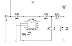
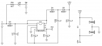
For projects with a charge pump (e.g., TC1044SCPA) for (positive) voltage doubling, why is there a capacitor between pin 4 (CAP-) and pin 2 (CAP+) before connecting to another cap positioned on the cathode of the Schottky diode after pin 8 (V+). Unless there's a negative voltage conversion, is the cap between pins 2 and 4 necessary? Also, is pin 4 needed at all in voltage doubling applications? The data sheet shows it as an NC for multiplier use cases.
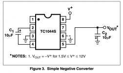
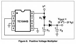
TC1044SCPA (Negative Converter).png

TC1044SCPA (Positive Voltage Multiplier).png

Powersound Power Stage.png
 
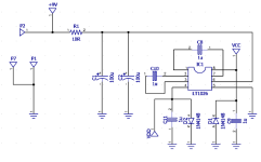
Another question here: Why do some charge pump blocks use 1uF caps instead of 10uF for the pump/reservoir caps? Doesn’t the reduced value negatively impact charge pump efficiency?
 
I'm not sure what the benefit would be unless it was simply to streamline the BOM, there isn't a heck of a lot of difference in physical size between the two.

The only real "benefit" I can think of would be inrush current (or maybe to reduce the amount of time of pump-up), but neither of those seem to be enough of an issue to justify it.

I've also seen some circuits that use 47uF or even 100uF throughout.

The Creation Audio Labs MK.4.23 Clean Boost uses 1uF capacitors as well, but it uses a different charge pump.
 
Back
Top