Charge Pump Board wiring

megatrav

Well-known member
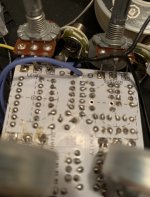
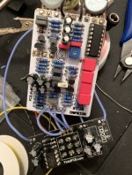
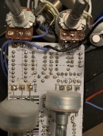
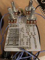
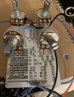
I am probably over thinking this, but I want to confirm that I am connecting the Charge Pump board correctly.
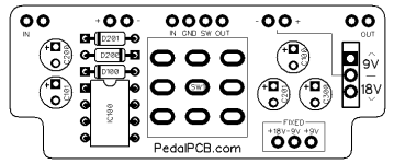
First, I see 2 ins and outs and neither appear to be for ground.
It also has 2 +/- holes on the top.
I am not planning on using a switch to change voltage, just wiring it for 18v.
Any help is appreciated!
 
Mostly the 18v pad at the bottom. Would I run a wire from the DC jack to that and the + on the top right?
 
The far left pad marked "IN" connects to your input jack.
The pad directly beside it is ground.

The far right pad marked "OUT" connects to your output jack.
The pad directly beside it is ground.

IN/GND/SW/OUT connect to the corresponding pads of the effect PCB (like the standard breakout board)

The +/- pads on the left side of the board connect to your DC jack.

The +/- pads on the right of the board are the switched DC supply that connect to the effect PCB. The voltage here depends on the setting of the switch.

The Fixed +18V, -9V, and +9V are the fixed output voltages, these are constant regardless of the switch setting.

---

In your case you'd want to connect the DC jack to the +/- pads at the top left of the board.

Connect the +18V pad at the bottom of the board to the + pad of the effect PCB.

Connect the - pad at the top right of the board to the - pad of the effect PCB. Alternatively you could connect the negative lug of the DC jack directly to the - pad of the effect PCB.
 
Last edited by a moderator:
The far left pad marked "IN" connects to your input jack.
The pad directly beside it is ground.

The far right pad marked "OUT" connects to your output jack.
The pad directly beside it is ground.

IN/GND/SW/OUT connect to the corresponding pads of the effect PCB (like the standard breakout board)

The +/- pads on the left side of the board connect to your DC jack.

The +/- pads on the right of the board are the switched DC supply that connect to the effect PCB. The voltage here depends on the setting of the switch.

The Fixed +18V, -9V, and +9V are the fixed output voltages, these are constant regardless of the switch setting.

---

In your case you'd want to connect the DC jack to the +/- pads at the top left of the board.

Connect the +18V pad at the bottom of the board to the + pad of the effect PCB.

Connect the - pad at the top right of the board to the - pad of the effect PCB. Alternatively you could connect the negative lug of the DC jack directly to the - pad of the effect PCB.
Thanks! So, should I leave the +/- on the left side empty?
 
Last edited by a moderator:
Just following up. I think I may have wired something wrong. I get bypassed tone but nothing when engaged.
Here is how I have it:
-18v on charge board going to DC jack
-Right side plus on charge board going to 9v on main pcb
-ground from right side going of board going to ground on pcb.
-ground from dc Jack going to ground on main board
 
Your DC jack should be wired to the +/- pads at the top left corner of the board.

18V pad should go to the + pad of the main PCB.
 
Your DC jack should be wired to the +/- pads at the top left corner of the board.

18V pad should go to the + pad of the main PCB.
Just to clarify.. should the DC Jack connect to the right and left side?
In the previous reply you said the DC Jack should connect to the +/- in the top right
 
Ahh yes, that was a typo. (The first part of the post was correct, then I went and contradicted myself later.... I've edited the post for clarity)

The top left +/- are for the DC jack.

The top right +/- are the switched output to your main PCB. Since you don't want the switched supply you can ignore the top right +/- pads.


There was a wiring diagram for this here at one point, I'll have to see if I can find it.
Sweet! Thanks for clarifying. I'll report back once I correct this.
 
I finally had a chance to rewrire and do some testing.
The good news is, it powers on!
The problem is, the LED stays on whether the effect is engaged or bypassed. The effect does turn on and off, but the LED stays lit.

I have the LED connected to the pads on the main board. Should it be wired differently? Or would it be something else?
 
That's how it should be wired. Disconnect the SW wire between the main PCB / charge pump PCB and see if the LED goes out.

If it goes out the problem is on the charge pump board (or the 3PDT itself).

If it remains lit there is a short of some sort on the main PCB.
 
Okay so I disconnected the SW cable and it remained lit.
So, I went over the solder joints and made sure nothing was touching or shorting out.
The SW cable is still disconnected, but now the light dims when I click the switch. It doesn't turn off completely? Very strange
 
Back
Top