Chop Shop. 1 works, other is a noise making robot

Barnshart

Member
Just got finished building 2 Chop Shops. The first one I made appears to works just fine, however the second one has far more gain and starts to squeal and oscillate if the gain or sag knobs go to high.

These are my first jfet builds, but I'm almost certain I understand the biasing. I am using the SMD J201's that Robert solderd on for me.

I am setting my DMM to read DC current on a setting that simply reads as "20" which I assume means 20v.

I take the red probe of the DMM and place it on the biasing pad on the PCB, and my black probe I'm putting onto the middle leg of where the throughhole equivalent of the SMD transistor would go. Ive dialed in both sets of transistors in my pedals to 6.66 with ease. I'm certain each pair of transistors in both pedals are biased identically....

So what gives? Any idea why one might be a super gainy squaling monster?

 
Show us a photo of the setting you are using on your meter. There are usually current and voltage settings. You need the DC voltage setting.

I am also pretty sure that you should be putting the red lead on the bias pad, and the black lead on a ground connection somewhere (ground of the power supply jack or an input/output jack should work)
I'll have to get to those pictures to tomorrow. But I will show you for sure.

Here's a video comparing both of them though.
 
Here’s what I did:

Sag pot full ccw
Dmm on dc voltage
Black probe in pedal screw hole
Red probe on the biasing test pad
Turn trimmer to desired voltage

Sag, gain and vol interact significantly in this circuit, but shouldn’t be giving you squeals and oscillation.
 
Here’s what I did:

Sag pot full ccw
Dmm on dc voltage
Black probe in pedal screw hole
Red probe on the biasing test pad
Turn trimmer to desired voltage

Sag, gain and vol interact significantly in this circuit, but shouldn’t be giving you squeals and oscillation.
You're describing exactly what I did do. It worked fine for the first one, seck d pedal not so much.
 
Looking at your photos the only thing I notice is that the tip contact for one of the input jacks is nearly touching the case. As far as I can work out it's on the good one, so it's obviously not actually touching and isn't an actual problem. I'd be moving it a bit to stop problems later down the track though.

Since you have a working one, and the problem seems to be associated with sag pot position, I think I would be measuring the voltages in the same parts of the circuit with the controls set to the same settings and see where there might be differences. If you find some differences in one part that will give some clues about where to look further.
 
Can you post a photo of the underside of the problematic board? It sounds like maybe you have a solder bridge or something that's causing a feedback loop/oscillation. If you figure out what you did wrong you can put it on a momentary footswitch and your bug becomes a feature.
 
Can you post a photo of the underside of the problematic board? It sounds like maybe you have a solder bridge or something that's causing a feedback loop/oscillation. If you figure out what you did wrong you can put it on a momentary footswitch and your bug becomes a feature.
Like the wave canon
 

Here's the red probe of the test pad and the black on ground. Is my DMM set to the right setting?


Looking at your photos the only thing I notice is that the tip contact for one of the input jacks is nearly touching the case. As far as I can work out it's on the good one, so it's obviously not actually touching and isn't an actual problem. I'd be moving it a bit to stop problems later down the track though.

Since you have a working one, and the problem seems to be associated with sag pot position, I think I would be measuring the voltages in the same parts of the circuit with the controls set to the same settings and see where there might be differences. If you find some differences in one part that will give some clues about where to look further.
 
Can you post a photo of the underside of the problematic board? It sounds like maybe you have a solder bridge or something that's causing a feedback loop/oscillation. If you figure out what you did wrong you can put it on a momentary footswitch and your bug becomes a feature.
I haven't got a picture of the back of the board. But I'm certain it's clean. I looked over everything and reflowed a few parts to be safe. Cleaned the back up with some isopropyl alcohol afterwards too
 
The meter is set to the correct setting. According to the schematic though, none of the transistor legs connect directly to ground, so you need a different place for the black probe. One of the ground connections for the power or audio jacks would work.
I've done that as well and it yields an identical reading
 
Im pretty sure this is an issue with the j201s. I had sinilar issues with mine. I replaced them with now ones on daughterboards, calibrated and it fixed the issue!
 
Im pretty sure this is an issue with the j201s. I had sinilar issues with mine. I replaced them with now ones on daughterboards, calibrated and it fixed the issue!
Well I guess I'm out of luck then, Robert on here was kind enough to reach out to me and solder some on for me before they shipped, but I have no extras and I don't have any SMD capable tools either.

Luckily I have a friend who loves noisy pedals so this one will likely be more appealing to him than a proper working one!

Guess we will call it "case closed" for now since I think you may be right 👍
 
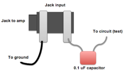
You could also use an audio probe to see where the bad one goes bad compared to the good one.
Have you tried audio probing yet?
Before trying to desolder parts this is a simple and useful way to see where this extra noise might be being generated from.

All you need is a 100n cap, some wire and a jack

1A79235C-6681-4483-9F17-63465CA5D632.png
If you have a looper pedal. Use that to generate some noise then place the test probe on the audio path of the circuit to see how the sound changes.
 
Well I guess I'm out of luck then, Robert on here was kind enough to reach out to me and solder some on for me before they shipped, but I have no extras and I don't have any SMD capable tools either.

Luckily I have a friend who loves noisy pedals so this one will likely be more appealing to him than a proper working one!

Guess we will call it "case closed" for now since I think you may be right 👍
Just buy some daughterboards and j201s from this site! It’s really not hard to solder SMD. I know it feels intimidating though
 
Back
Top