SOLVED Chop Shop Biasing

Ctrl4Smilerz

Well-known member
I just finished boxing up the my Chop Shop, and I'm having some trouble biasing the jfets. I have my multimeter on this setting:
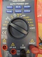
PXL_20230305_230435585.jpg

Putting the black probe on the threads of a screw hole, and touching the red probe on the biasing pad, with the sag all the way CCW I get 3.3-4.9 volts on Q1, and 4.4-5.0 volts on Q2, but it jumps around a lot. I read elsewhere that you want 6 volts. Also when plugged in, I don't get any sound when engaged (not sure if that is related to the bias, or another problem). Here is the board:
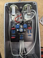
PXL_20230305_230354940.jpg


As always your help is very much appreciated :)
 
This is very picky about J201's being within the required IDSS.
Where did you get your J201's ???

From the Builder, Thanks Guillaume - FC :
Let's start by sorting the JFETS. As we saw on the datasheet, J201's can have an Idss value from 200uA to 2mA. That is a huge range. For Q1, you want a J201 that has an Idss from 600-800 uA. For Q2, you want one with Idss about 400-600uA.
So you'll have to see what you have to work with. You might be unlucky and have all J201's with crazy values like 1500uA. In that case, the drain resistors will need to be changed.
I got them from Mouser.
 
And if the signal jumps around a lot it could be that your ground probe isn't making firm contact. Sometimes flux or crud or whatever gets in the way of the probe, and if you just leave the black probe in the screw hole it might not be making good contact.
 
In the photo, both trimmers are in the maximum CCW position - so they have maximum resistance. This gives the lowest possible voltage on the drain (test point). You should set the Sag to the highest voltage (max CCW) and rotate the trimmers to set the bias voltage. Maybe that's what you're doing, but it's not clear from your description. I assume you have J201, the picture does not show what model of transistor it is.
 
Thanks. In DC volts it's between 0.2 and 4.5 volts, still far of from 6.
Take a closer look at your 33k resistors, I think they are 33 ohms???
Orange, Orange, Black, Red, Brown = 33K

Check all your Resistors with this.
Click On Bands fo 5 colours :

Edit
Can you confirm that your Trimmers are 50K ie 503 written on the side.
 
Last edited:
Take a closer look at your 33k resistors, I think they are 33 ohms!???
Orange, Orange, Black, Red, Brown = 33K
Indeed, but look at the schematic. Whether it's 33R, 3k3 or 33k - it doesn't really matter when setting drain voltage.

Same with no sound. Even if it was 330k, there should be "something" on the output.
 
Is the little blue cap below the middle pot soldered in properly?
Doubled checked, and it is. I reflowed it from the other side just to be sure.
In the photo, both trimmers are in the maximum CCW position - so they have maximum resistance. This gives the lowest possible voltage on the drain (test point). You should set the Sag to the highest voltage (max CCW) and rotate the trimmers to set the bias voltage. Maybe that's what you're doing, but it's not clear from your description. I assume you have J201, the picture does not show what model of transistor it is.
Yes, this is how I measured.
Take a closer look at your 33k resistors, I think they are 33 ohms???
Orange, Orange, Black, Red, Brown = 33K

Check all your Resistors with this.
Click On Bands fo 5 colours :

Edit
Can you confirm that your Trimmers are 50K ie 503 written on the side.
Checked this with a multimeter and you are right they are 33R not 33K. Good eyes, I will fix it.

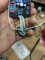
Also I ran out of 3PDT breakout boards, so I wired this pedal by hand. Could that be why there is no sound when engaged?
PXL_20230306_132213239.jpg
 
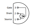
This has been mentioned before but I don't know if we ever got a definitive answer (and by that, I mean someone actually using them throwing one on a semiconductor tester and verifying)...

The datasheet for the InterFET J201's currently sold by Mouser shows the pinout all wrong.

1678111173128.png

This would be SDG, where the correct pinout should be DSG.

Has anyone used these and can confirm whether the datasheet is incorrect or the pinout is indeed different?
 
This has been mentioned before but I don't know if we ever got a definitive answer (and by that, I mean someone actually using them throwing one on a semiconductor tester and verifying)...

The datasheet for the InterFET J201's currently sold by Mouser shows the pinout all wrong.

View attachment 43427

This would be SDG, where the correct pinout should be DSG.

Has anyone used these and can confirm whether the datasheet is incorrect or the pinout is indeed different?
I'd be happy to test mine, if you can explain how you test it.
 
I contacted Mouser about Interfet j201's & the engineer??? told me that the Drain & Source are interchangeable?????????????????????????
That's when I purchased NOS Siliconix, Vishay & Smallbear short leg J201's that are the correct pinout.
When they runout, I will probably have to purchase SMD from PedalPCB???
 
Back
Top