SOLVED Chop Shop gain not working

SYLV9ST9R

Well-known member
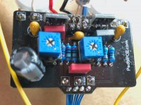
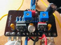
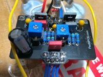
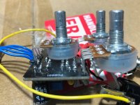
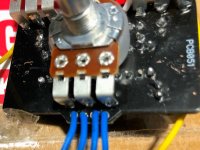
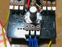
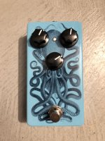
Hi guys, I’ll be looking at one of my first build, as the gain/drive pot stopped working on this Chop Shop.
Volume and Sag seem to be working fine, but an overdrive without the drive is a bit pointless.
As I’m still a noob when it comes to troubleshooting, I was just wondering if someone had any hindsight of things I should be looking at, or if I should just replace the potentiometer.
I’ll take it apart one night this week, but from visual inspection, the soldering seems fine.
 
You can use a multimeter in resistance (ohms) mode to measure the resistance between the pins of the gain pot, before even disassembling. This should tell you if the potentiometer needs replaced.

From pins 1 to 3 should be around 100kohms no matter what. From 1-2 and 2-3 should both change from close to zero ohms to 100kohms based on where the knob is set.
 
Here are some not so great pics. A bit hard to see with the trimmers.
It was my second build, so you can see a good example of the way those alligator clips chew through the board, but I don't think it touches anything he
I reflowed the gain pot pad, as it looked a bit off, but to no avail (and also because I don't have a multimeter, might be a good moment to get one). Might just get a new one from a local shop, as I need some stuff from them if nothing seems wrong.
I've included a pic of the pedal itself, as it's the first one I boxed (I think this is the 3rd decal I applied on it) and I just love the way it looks.
It now belongs to a good friend and he nailed it on the design. It's probably my favorite build, visual-wise (probably because I didn't design it ).
 

Attachments

  • IMG_6710.jpg
    IMG_6710.jpg
    308.6 KB · Views: 67
  • IMG_6711.jpg
    IMG_6711.jpg
    292.4 KB · Views: 71
  • IMG_6712.jpg
    IMG_6712.jpg
    380.4 KB · Views: 64
  • IMG_6714.jpg
    IMG_6714.jpg
    462.2 KB · Views: 49
  • IMG_6715.jpg
    IMG_6715.jpg
    310.6 KB · Views: 37
  • IMG_6716.jpg
    IMG_6716.jpg
    246.5 KB · Views: 39
  • IMG_6709.JPG
    IMG_6709.JPG
    480 KB · Views: 58
It looks to me like your 2N222 emitter should be on the other side, as far as I know with incorrect orientation it would still conduct but affect hFE etc but I'm no expert

Continuity check the emitter pin (with the small metal tag) connects to volume 3 as in the schematic

I use the shop pcb images to check traces if I don't have the pcb and it defo looks like emitter goes to the left looking at your images it looks like yours goes to the right I'd also reflow any ball like joints which could be dry inside

chopschem.jpg choppcb.jpg
 

Attachments

  • choppcb.jpg
    choppcb.jpg
    183.3 KB · Views: 4
Looks like you're right. Greatly appreciated.
I'm sure I had verified, but I could have been totally wrong there, no doubt.
As the pedal was working (until early December), I was sure I had it right and sound-wise, I had compared it to my Modèle B and it sounded about right.
 
It looks to me like your 2N222 emitter should be on the other side, as far as I know with incorrect orientation it would still conduct but affect hFE etc but I'm no expert

Continuity check the emitter pin (with the small metal tag) connects to volume 3 as in the schematic

I use the shop pcb images to check traces if I don't have the pcb and it defo looks like emitter goes to the left looking at your images it looks like yours goes to the right I'd also reflow any ball like joints which could be dry inside
Looks like you're right. Greatly appreciated.
I'm sure I had verified, but I could have been totally wrong there, no doubt.
As the pedal was working (until early December), I was sure I had it right and sound-wise, I had compared it to my Modèle B and it sounded about right.
 
As I said I'm not technically proficient more a hobbyist but it would work the wrong way round in some situations I would maybe socket it incase it has been damaged using it like that for an extended period, it looks like a common collector set up in the schematic with the collector common to the input (base) and output (emitter) so usually a buffer but idk 100% you'd need someone who knows what they're talking about

BJT's are pretty robust so it may be all good especially at these voltages
Will do that (socket it), I think I have an extra one lying around to try so might do that if changing the orientation doesn’t fix it.
 
As I said I'm not technically proficient more a hobbyist but it would work the wrong way round in some situations I would maybe socket it incase it has been damaged using it like that for an extended period, it looks like a common collector set up in the schematic with the collector common to the input (base) and output (emitter) so usually a buffer but idk 100% you'd need someone who knows what they're talking about

BJT's are pretty robust so it may be all good especially at these voltages
Thanks, it did the trick!
 
You can use a multimeter in resistance (ohms) mode to measure the resistance between the pins of the gain pot, before even disassembling. This should tell you if the potentiometer needs replaced.

From pins 1 to 3 should be around 100kohms no matter what. From 1-2 and 2-3 should both change from close to zero ohms to 100kohms based on where the knob is set.
Would this also apply to the Sag potentiometer (except at the Sag pots 10k value)? I’m getting some strange readings from pins 1 to 3 on the Sag pot, it I couldn’t remember if these resistance readings could be taken if it was already in the circuit. Thanks!
 
You can. You only need to measure between pins 1-2 since pins 2-3 are connected. Should smoothly go from near 0 ohms to bear 10kohms. You can measure this resistance in circuit, but without power.

If you’re having trouble with the sag pot, that is sometimes an issue using out of spec jfets, though I don’t know where you got yours (smd is usually great, I think people have had good results with mouser through hole j201s. Jfets from eBay are generally not good).
 
Thank you! I may have an issue with the B10K pot, and I should’ve checked it before I soldered it. I’ll try to swap it out. I’m using the presoldered SMD from PedalPCB, but I’ve used the Mouser InterFET J201s with success in the past also.

I’m experiencing gradual loss of volume without moving any of the pots and virtually no gain. I checked continuity according to the schematic, and everything buzzed out fine.
 
How about you measure some voltages before changing anything?
What are the drain voltages on Q1 & Q2 with SAG fully counterclockwise?
Q1 & Q2 can be in-spec and still not work right in this pedal.
Drain voltages with the SAG fully CCW are 7.45V and 7.19V on Q1 and Q2, respectively. Incoming power is 9.22V at the jack. Thanks!
 
Drain voltages with the SAG fully CCW are 7.45V and 7.19V on Q1 and Q2, respectively. Incoming power is 9.22V at the jack. Thanks!
If I'm not mistaken, the desired bias point should be around 6.6v (I also saw 2/3 of the supplied voltage which would be nearer 6v) at the drain voltage. Then again, having no multimeter, I adjusted the trimpot I replaced the drain resistors with by ear (with my Modèle B for reference).
 
Last edited:
Back
Top