SOLVED Circulator loud popping issues

jwyles90

Well-known member
Hey all!

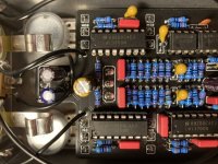
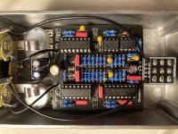
I just finished putting together the Circulator build (using a few of Chuck’s mods), and it’s making a pretty substantial pop every time I engage or disengage the pedal. Outside of that everything works as advertised and it sounds great, but the pop is a pretty big bummer.

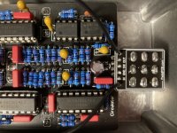
I used some Tantalum caps that I had on hand since they were the only things that would fit for the 1uF caps, and I’ve never used those before so I’m wondering if maybe they have something to do with it? Does anyone else out there have any tips for isolating whatever could be causing a pop like that? My solder joints all look pretty good to my eyes, but if there’s something obvious that jumps out to you all that I’m not seeing, please let me know! Thanks!
7CB0CAD9-EB11-4E85-A5EC-2393CEA72A60.jpeg 4B134840-3EAC-4B12-8E30-020D932887E8.jpeg 3EFCD02C-1151-4F12-ACEB-B506A1B0CAD0.jpeg
 
Woke up this morning and realized that Tantalum caps are polarized, so I would imagine that that could probably be the culprit? So I guess my question is are these caps ok to use? And if they’re polarized, do they need to all be in the same orientation since there’s no polarization marker on the board?
 
I personally wouldn't use tantalum in place of ceramic or film capacitors even though you can

Tantalums are indeed polarized electrolytic capacitors and you obviously have to get the polarity correct

Normally with tants there's a good chance they'll just blow if you get polarity wrong but not always so maybe you've got that right

Check you have them all in the correct polarity most positive voltage to + side you'd need to work it out from the schematic

I'd also check the solder joints on your power supply capacitors C100, 101 and 102
Yea this was a good lesson in making sure I understand a component before just throwing it in there. I’ve never used tants before and figured a value is a value, lesson learned!

For checking positive voltage I’m assuming I set the DMM to the DC volts range and measure both leads with that? Sorry if that’s a silly question, I’m still getting the hang of all the different ways to measure stuff with this thing.
 
I should have said it may not be the caps but that's the first thing I'd check

Could be the LED or R2 with a dry joint perhaps try reflowing the joints on R2 and the caps test it, if it still pops disconnect the LED see if that stops it

For polarity you want + to the most positive side negative to the side nearest ground you don't have to take voltages for example I'd say C2 + side to R1
 
Before you start melting solder, we're going to do some inspection and make some measurements.

What do you have plugged into the Circulator's input and output jacks?

Popping on engage & disengage can usually be traced to a missing anti-pop resistor or a leaky cap at the input or output. Since you say it happens on both engage and disengage, the output side of the pedal is the most likely location for the problem.

Make sure the - end of C9 goes to the output. Use a DMM to measure continuity with the power off.

Make sure R26 is 100K and both ends are soldered to the board. Inspect it visually and measure the resistance from the OUT jack tip to ground with the power off and pedal engaged. Measurement should be 100K.

C2, polarity doesn't matter since both ends of the cap are at the same DC voltage.
C7, the + end of the cap should connect to IC2-9.
C10, the + end of the cap should connect to IC5-6.
C11, the + end of the cap should connect to IC1-13.

I do not recommend aluminum caps for C13 & C14, but if the LFO in yours works at the slowest RATE, then you don't need to change them out.
Ok so if I'm understanding your first question correctly, I've got just my guitar plugged into input and my amp into output.

I checked continuity for C9 and I got the beep only when I was touching the positive end (the side with the little dimple at he top of the cap) to output. I'm assuming that should be reversed?

Visually R26 is a 100k resistor (double checked the bands). The measurement from outjack tip to ground was 98.9.
C7+ connected to IC2-9 in continuity mode.
C10+ seems to be connected, although I had to put the probe lead in between legs 6 & 7 to get a beep.
C11+ seems to be connected as well, although I had to do the same thing as C10 to get a connection.

Overall the LFO seems to be working properly, or at least I don't hear anything not modulating where it seems like it should be.
 
Ok so if I'm understanding your first question correctly, I've got just my guitar plugged into input and my amp into output.
That's good, just wanted to make sure nothing else might be causing the popping.

I checked continuity for C9 and I got the beep only when I was touching the positive end (the side with the little dimple at he top of the cap) to output. I'm assuming that should be reversed?
Yes, reverse C9. That should fix the problem.

Visually R26 is a 100k resistor (double checked the bands). The measurement from outjack tip to ground was 98.9.
That's good.

C10+ seems to be connected, although I had to put the probe lead in between legs 6 & 7 to get a beep.
That's not right. You must have been touching pin 6 when it beeped. Pin 7 won't beep.

C11+ seems to be connected as well, although I had to do the same thing as C10 to get a connection.
I don't think you're putting the probe between the pins. Only pin 13 will beep.
 
That's good, just wanted to make sure nothing else might be causing the popping.


Yes, reverse C9. That should fix the problem.
I’ll give it a shot! That particular spot on the board looks like it’s got enough room for a box cap (although it’s a bit of a squeeze). Would it be better to put one of those in there if I can manage it? Or should I stick with tantalum for uniformity’s sake?
I don't think you're putting the probe between the pins. Only pin 13 will beep.
That makes sense. I’m sure that’s what’s happening, it just seemed like it would only beep in between the pins.
 
Back
Top