
BuddytheReow
Breadboard Baker
Hey Guys!
I thought it would be a good idea for all of us to contribute as many of the more common mods out there into one centralized area. I wanted to take some time to write down my thoughts. These mods are mostly for dirt pedals (distortion, OD, fuzz). There are tons more out there, but here are some to get you guys started.
Here is my number one "rule" when it comes to mods:
They can make the circuit sound better, they can make the sound worse, or they can do nothing. You won't know until you try!
Ok, not really a 'rule', but definitely something you should keep in the forefront of you mind when trying out mods. Also keep in mind that any mod you do might sound great to you and crappy for someone else. Some love the gnarliest distortions ever and some love just the slightest amount of dirt in their overdrive to make their guitar sing. It is all subjective.
Enough intro talk. Let's mod!
Swapping out components for different values
One of the most direct mods you can do is to simply swap out a component with another one of a different value. See that 100n right at the beginning of the circuit after input? Why not try putting a 10n or 1n in there instead. The gain pot in the schematic has a value of 100k? Try putting in a 50k, 250k, or maybe even a 1m pot!
One caveat to this: you should know or at least have a general idea what that component is doing in the circuit. Reading into circuit analyses of the more common pedals and/or some theory will definitely give you an edge here.
Pulling components out entirely
Sometimes pulling a component out and not substituting will have an effect on the sound too. You may even kill the signal altogether. Try pulling out that lonely capacitor going to ground in the beginning or end of a circuit. You never know until you try.
Power Section
Power sections (usually but not always) have a diode for polarity protection (blocks user error) and at least 1 capacitor to "clean" the incoming power. There may also be some resistors to slow the voltage down a bit or a voltage divider to turn your 9v into 4.5v. The LED is merely an indicator that power is on. You can alter the resistor value right next to that til your heart's content since that alters the brightness of the LED.
My general rule of thumb is to leave the components in the power section alone. That being said, you can definitely alter the INPUT voltage to see how a circuit sounds. If you are going to increase the voltage above 9v make sure all the components in the ENTIRE circuit can handle that voltage. Electrolytic capacitors are at the top of the list here. As good practice, whatever voltage you want to put into your circuit make sure all your components can handle double that. Check the datasheets for the opamps too to make sure they will work. In certain analog delay pedals, the PT2399 chip only runs on 5v and that is controlled by a voltage regulator component, so changing the main input voltage won't do a whole lot.
Certain fuzz pedals can sound TOTALLY different if you start dropping the input voltage. This can be done by wiring up a potentiometer (the pot is labelled "starve" in certain schematics). Pin 3 to your regular input source (9v) and pin 2 into the circuit/transistor. When it is fully clockwise you've got full voltage; as you go CCW the voltage will drop since there is increased resistance to the incoming power. Sometimes altering the voltage will do nothing or you will get total silence. You won't know until you try.
Clipping Diodes
This is an excellent article that explains clipping diodes in nearly all overdrive, distortion, and (maybe) certain fuzz pedals. You can read it here, but I will also sum up hard clipping, soft clipping, and how the different diodes behave using a lot of what mentioned in the article for those that don't want to read it cover to cover.
https://www.guitarpedalx.com/news/news/a-brief-hobbyist-primer-on-clipping-diodes
Hard Clipping vs Soft Clipping in a schematic
Tone Stacks/Filters will be explained in the next section. For now, think of it as your EQ block. Just pay attention where the diodes are in relation to the other components.

For soft clipping sound, think TubeScreamer. Hard clipping sound, think Proco Rat or Dist + and the resistor in parallel with the diodes in the picture is optional IMO. Try it and see how you like it. Depending on the circuit you are putting together you can actually add either of these clipping sections or both. Add a switch to either to see if you like the clipping on or off. You be the judge.
Diode Types
This is a decent reference for how different types of diodes react in a clipping circuit. It is found in the link above. You may mix and match to see what sounds good to you. LEDs may sound great as hard clippers but crap as soft clippers.
Depending on how many diodes you wan to put into your clipping block (yes, you can put more that 2) you may want to consider whether to clip symmetrically or asymmetrically. The example I'm using below is the hard clipping type, but the concept is the same for soft clipping. You can mix and match different diode types to see what it is you like.

Testing them out on a breadboard
Want to try out these different diode mods on a breadboard? Here's some help! The pdf can be found here from Beavis Audio. I don't agree with how the asymmetrical clipping is presented, but it's still a good reference. http://beavisaudio.com/beavisboard/projects/bbp_DiodeMods.pdf

Tone Filters
As I'm writing this I realize that this section can really be it's own post and can get rather extensive once you start talking about the various tone stacks out there. I will do my best to hit the high points here.
Filters in a schematic
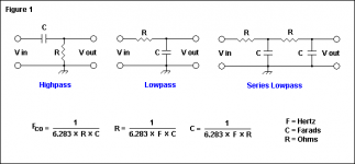
If you see this in a schematic it is an EQ filter. Depending on the order of the resistor or capacitor, it is either a Low Pass or High Pass filer

Low Pass Filter - anything below a certain frequency determined by the combination of values for the resistor and capacitor will go through the circuit.
High Pass Filter- anything above a certain frequency determined by the combination of values for the resistor and capacitor will go through the circuit.
Want to know the frequency that will be affected, called the cutoff or corner frequency? Use this R-C Filter Calculator. The general mod rule here is you should increase or decrease the value of one component with relation to the other. Increase or decreasing the values of both won't really affect anything. A pot and/or a rotary switch can be very valuable here to see what you like.
Filter in an opamp feedback loop
This is one of my favorite mods to do using an opamp in a dirt pedal. Let's take a look at a section of the Distortion + schematic from Beavis Audio.

I'm highlighting part of the "tone" section of a negative feedback loop in the opamp circuit. Simply changing the value of C4 listed here will alter how much bass gets amplified by the opamp. See the tone filter like we talked about above? The orientation is a bit different than in the original picture.
I'm done writing for the day, but I think this is a great start for anyone who wants to start modding. If anyone else has other great mods please share them here. The more "general" mods we have in one place the better!
Enjoy the journey!
Thanks,
BuddyTheReow
I thought it would be a good idea for all of us to contribute as many of the more common mods out there into one centralized area. I wanted to take some time to write down my thoughts. These mods are mostly for dirt pedals (distortion, OD, fuzz). There are tons more out there, but here are some to get you guys started.
Here is my number one "rule" when it comes to mods:
They can make the circuit sound better, they can make the sound worse, or they can do nothing. You won't know until you try!
Ok, not really a 'rule', but definitely something you should keep in the forefront of you mind when trying out mods. Also keep in mind that any mod you do might sound great to you and crappy for someone else. Some love the gnarliest distortions ever and some love just the slightest amount of dirt in their overdrive to make their guitar sing. It is all subjective.
Enough intro talk. Let's mod!
Swapping out components for different values
One of the most direct mods you can do is to simply swap out a component with another one of a different value. See that 100n right at the beginning of the circuit after input? Why not try putting a 10n or 1n in there instead. The gain pot in the schematic has a value of 100k? Try putting in a 50k, 250k, or maybe even a 1m pot!
One caveat to this: you should know or at least have a general idea what that component is doing in the circuit. Reading into circuit analyses of the more common pedals and/or some theory will definitely give you an edge here.
Pulling components out entirely
Sometimes pulling a component out and not substituting will have an effect on the sound too. You may even kill the signal altogether. Try pulling out that lonely capacitor going to ground in the beginning or end of a circuit. You never know until you try.
Power Section
Power sections (usually but not always) have a diode for polarity protection (blocks user error) and at least 1 capacitor to "clean" the incoming power. There may also be some resistors to slow the voltage down a bit or a voltage divider to turn your 9v into 4.5v. The LED is merely an indicator that power is on. You can alter the resistor value right next to that til your heart's content since that alters the brightness of the LED.
My general rule of thumb is to leave the components in the power section alone. That being said, you can definitely alter the INPUT voltage to see how a circuit sounds. If you are going to increase the voltage above 9v make sure all the components in the ENTIRE circuit can handle that voltage. Electrolytic capacitors are at the top of the list here. As good practice, whatever voltage you want to put into your circuit make sure all your components can handle double that. Check the datasheets for the opamps too to make sure they will work. In certain analog delay pedals, the PT2399 chip only runs on 5v and that is controlled by a voltage regulator component, so changing the main input voltage won't do a whole lot.
Certain fuzz pedals can sound TOTALLY different if you start dropping the input voltage. This can be done by wiring up a potentiometer (the pot is labelled "starve" in certain schematics). Pin 3 to your regular input source (9v) and pin 2 into the circuit/transistor. When it is fully clockwise you've got full voltage; as you go CCW the voltage will drop since there is increased resistance to the incoming power. Sometimes altering the voltage will do nothing or you will get total silence. You won't know until you try.
Clipping Diodes
This is an excellent article that explains clipping diodes in nearly all overdrive, distortion, and (maybe) certain fuzz pedals. You can read it here, but I will also sum up hard clipping, soft clipping, and how the different diodes behave using a lot of what mentioned in the article for those that don't want to read it cover to cover.
https://www.guitarpedalx.com/news/news/a-brief-hobbyist-primer-on-clipping-diodes
Hard Clipping vs Soft Clipping in a schematic
Tone Stacks/Filters will be explained in the next section. For now, think of it as your EQ block. Just pay attention where the diodes are in relation to the other components.
For soft clipping sound, think TubeScreamer. Hard clipping sound, think Proco Rat or Dist + and the resistor in parallel with the diodes in the picture is optional IMO. Try it and see how you like it. Depending on the circuit you are putting together you can actually add either of these clipping sections or both. Add a switch to either to see if you like the clipping on or off. You be the judge.
Diode Types
This is a decent reference for how different types of diodes react in a clipping circuit. It is found in the link above. You may mix and match to see what sounds good to you. LEDs may sound great as hard clippers but crap as soft clippers.
- Schottky - Very High Distortion, Maximum Compression
- Germanium - High Distortion, Significant Compression
- Silicon - Classic/Standard Overdrive and Distortion - some degree of Compression
- LED - Very Open and Dynamic Saturation - Least Compression and Distortion
Depending on how many diodes you wan to put into your clipping block (yes, you can put more that 2) you may want to consider whether to clip symmetrically or asymmetrically. The example I'm using below is the hard clipping type, but the concept is the same for soft clipping. You can mix and match different diode types to see what it is you like.
Testing them out on a breadboard
Want to try out these different diode mods on a breadboard? Here's some help! The pdf can be found here from Beavis Audio. I don't agree with how the asymmetrical clipping is presented, but it's still a good reference. http://beavisaudio.com/beavisboard/projects/bbp_DiodeMods.pdf
Tone Filters
As I'm writing this I realize that this section can really be it's own post and can get rather extensive once you start talking about the various tone stacks out there. I will do my best to hit the high points here.
Filters in a schematic
If you see this in a schematic it is an EQ filter. Depending on the order of the resistor or capacitor, it is either a Low Pass or High Pass filer
Low Pass Filter - anything below a certain frequency determined by the combination of values for the resistor and capacitor will go through the circuit.
High Pass Filter- anything above a certain frequency determined by the combination of values for the resistor and capacitor will go through the circuit.
Want to know the frequency that will be affected, called the cutoff or corner frequency? Use this R-C Filter Calculator. The general mod rule here is you should increase or decrease the value of one component with relation to the other. Increase or decreasing the values of both won't really affect anything. A pot and/or a rotary switch can be very valuable here to see what you like.
Filter in an opamp feedback loop
This is one of my favorite mods to do using an opamp in a dirt pedal. Let's take a look at a section of the Distortion + schematic from Beavis Audio.
I'm highlighting part of the "tone" section of a negative feedback loop in the opamp circuit. Simply changing the value of C4 listed here will alter how much bass gets amplified by the opamp. See the tone filter like we talked about above? The orientation is a bit different than in the original picture.
I'm done writing for the day, but I think this is a great start for anyone who wants to start modding. If anyone else has other great mods please share them here. The more "general" mods we have in one place the better!
Enjoy the journey!
Thanks,
BuddyTheReow
")


