Could someone help a newbie with wiring a 4P3T Rotary Switch?

Rygar138

New member
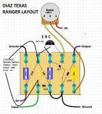
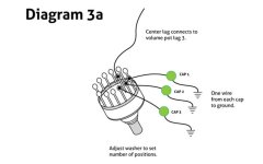
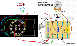
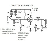
Hi! I really hope that someone can help me out. I've been diving deep into learning how to build pedals and other circuits over the last couple of months, mostly at the breadboard stage. I originally started because I was interested in building a Diaz Texas Ranger (aka Pedal Pawn Texan Twang). I've been using the below schematic as well as a couple of diagrams, but where I ultimately get hung up is at the 3 way rotary switch (I have a 4P3T switch). Could anyone help me in simple terms to A: learn how the switch should be wired in regards to the schematic and the caps listed, and B: to understand how that is deciphered through looking at the schematic? It seems like there should be enough info with the diagrams below, but I'm about 10 breadboard attempts in, and can't seem to make it work.

I would be forever grateful for any help, because I've been scouring the internet, and while I found a couple of forum posts here and elsewhere, I was having trouble deciphering. This has been a headache for long enough that it's time to ask for help, and I apologize if this is the wrong place.

Attached is:
The schematic
A diagram that I cannot vouch for the correctness of, but was helping me to understand how the wiring works
A diagram of wiring the 3 way rotary switch, which I could not get to work after several attempts

Thank you for reading!
Diaz Texas Ranger Schematic.jpeg Diaz Texas Ranger Layout.jpeg 3 Way Rotary Switch Wiring.jpeg
 
Were you wiring it to ground as in the diagram for the rotary? In the circuit it looks like you'd take a wire from the input to the caps as on the middle diagram, then from the center rotary lug to the next part of the circuit, the junction of the 68k. 470k, and transistor base. Make sure with some continuity tester on your rotary you're using the correct terminals if you have a rotary with a bunch of lugs and it should fire right up. Let me know if this isn't clear!
 
Hi Swyse, thank you so much for your help!

First, I tried exactly as the rotary diagram displayed, center lug to pot lug 3, and the three connections on the switch to one end of each corresponding cap, and the other end of each cap to ground. After that I tried doing the same, but also making the connections shown on the diagram.

I believe both of those attempts had a signal when tested, but muted, and on only one position on the switch, the other (2) positions lost the signal completely.

As I understood from the middle diagram (very likely incorrectly understood haha), the .1uf (lo) capacitor connection on the switch would connect to the input, and the .005uf (high) capacitor connection on the switch would connect to the 470k/68k caps connection. Should the input be connecting to *all* of the caps, and not just the opposite one that connects to 470k/68k?

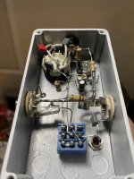
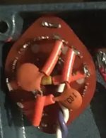
Also, to avoid mixups, this is the model of the rotary switch that I'm using. I also found these two photos of the inside wiring of the Texas Ranger, and it looks like they are wiring differently than the rotary diagram that I originally shared. Would that be because they are using a different style of rotary switch?
Ranger Inside.jpeg Ranger Rotary Switch.jpeg

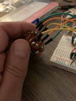
-or- should i be wiring the capacitors to the opposite poles, like this? I have two switches, and decided to solder the connections on one of them when attempting this method. I soldered wires on the opposite pole connections of each position, and connected both corresponding sides to each cap, trying to mimic what I at least thought I was seeing in those photos. The center pin isn't soldered in my photo, but I connected that to the board with an alligator clip when I attempted. This attempt had no signal at all when I tested.

IMG_4496.JPG

Thanks again for commenting, I really do appreciate it!

Cheers!
-Ryan
 
You could totally use multiple poles on the switch to do it if you wanted instead of wiring the input to all the capacitors separately, it all works the same really. It is a little neater if you're floating the whole thing in an enclosure since you would have two tie points. Pardon the crudity of the drawing, but this is how I would wire it if you have a shorting switch (which I believe you have, but not sure based on the link), if its non shorting I'd wire the 5n on the board instead of the switch and leave that pole unpopulated then I'd put another 5n where the 10n is and leave the 100n where it is, so in parallel your capacitor values would be 5n then 5n+5n for 10n and then 5n+100n for 105n, but this is just a small user experience thing because your signal wouldn't cut out when turning the switch. Either way you go, once again make sure you are using the correct poles on the switch! Edit: I should add that this might work backwards to how you would intend it, so you may have to switch the 5n and 100n if it works backwards to how you want


1662257549382.png
 
Incredible, thank you so much for making that illustration, that makes it so much clearer. And I just started playing around with combining caps in serial/parallel to get different values, so I'll have to play around with that. I'm still in breadboarding phase are the moment, but that's exactly why!

I'm not entirely new to multimeters, but I am somewhat new to using continuity, but I did play around with it after making my last post. I was testing the switch in the photo that has wires soldered to each side like your drawing, and determined that the opposite sides (green/green, yellow/yellow, etc) are *not* connected, regardless of the switch position. Does that determine if it is a shorting or non-shorting switch? Or is there another way for me to test which one I'm working with?
 
For example shorting would be if the green and blue (poles 1 and 2) connect as you turn the switch before it fully switches over, the poles short together due to the contact inside the switch being a little longer so it touches both before fully switching.
 
For example shorting would be if the green and blue (poles 1 and 2) connect as you turn the switch before it fully switches over, the poles short together due to the contact inside the switch being a little longer so it touches both before fully switching.
Ah-ha, gotcha! I read about shorting v non shorting before but couldn't make sense of it. I really can't tell you how much all of this helps. Thanks again, you're the best!
 
Back
Top