Dark Rift Delay

digitalsea

New member
Hi all,

Tearing my hair out with this one.

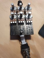
I’m only getting clean signal when engaged. I’ve switched out all the ICs and checked over too many times.

Is there anything that you guys can see that I’m missing?

Thanks for looking. 0F2B35EA-652B-439B-B36C-A561CEA9F29C.jpeg
 

Attachments

  • 577CC598-5BD9-4696-BC0A-D4DC82AA225F.jpeg
    577CC598-5BD9-4696-BC0A-D4DC82AA225F.jpeg
    1.3 MB · Views: 71
Nothing stands out can't fully see R11, 16, 20, 31 and 32 and obviously can't see capacitor values

The only other thing I notice is that D2 and 3 orientation differs from your silkscreen to the pcb image those I think just limit / clamp feedback

What's your PT2399 voltages
 
I believe Mcknib nailed it on D2 and D3! Remove both and try the circuit without the diodes, if you have a wet signal without the diodes in the circuit, then replace them in the opposite direction of the silk screen. On the schematic the anode of the diodes is connected to ground, the way the PCB looks, the cathode is connected to ground. You can see this in your picture by looking at the cathode of D2 and R5 which is just to the left of D2. They both have the 4 points connected to the ground plane of the PCB. If the diode is reversed you will short your wet signal to ground.

0F2B35EA-652B-439B-B36C-A561CEA9F29C.jpeg

DRD.png
 
If the diode is reversed you will short your wet signal to ground.
I thought that may well be the case signal getting dumped to ground but also thought it might be a layout update

Maybe @PedalPCB could let us know if it's a layout thang

You can simply continuity check D2 and 3 cathodes connect to C7 and repeats lug 2 as they should or even easier as @Chas Grant says check both anodes go to ground
 
There was a batch of boards where D2 was reversed but it didn't cause any issues.

These are just to limit the feedback loop, it's a typical diode-to-ground hard clipping arrangement.


This is the correct orientation, but even if one (or both) were installed incorrectly it wouldn't cause a "no signal" condition.

1603980878105.png

More importantly, your board is not one of these. Yours is the current revision so you should follow the silkscreen on the board.
 
Thanks all. Apologies for the delay in replying, had work. Appreciate the responses.

I’ve clipped D2 and D3 to remove them from the circuit and can confirm that @PedalPCB is correct and isn’t the issue here.

I’m going to learn how to use a multimeter and report back. Might take me a hot minute.
It’s weird. I’ve built a good dozen or so from pedalpcb and never had anything like it.

‘Thanks again
 
What's that sticking up amid the Pots on the left?
That’s a green led that was connected to pin 7 in order to solve the noise issue. There is a good thread where a user solved the noise issue by connecting these up. I thought that was the problem initially, so I clipped the connection to pin 7, but have left the led connected to ground in the interim. The led legs are not touching any pads or the like, so shouldn’t be causing an issue. Unless someone points out it’s a problem? No issue to remove it
 
It wouldn’t be an issue with the chip specs I’ve used? I note that I’ve used an lm324N and a 833N. Whereas the build docs call for lm324A?

I did a quick google prior to using them and didn’t see anything that I thought would be a problem, but I’m happy to be wrong
 
Most of the lettering after IC part numbers is manufacturer code usually for package type like N you'll also see stuff like UB for unbuffered B buffered L leaded and so on, some datasheets list package types etc

So it doesn't make a difference in your case as you say
 
I'm also having this issue. When the pedal is on there is a boost in volume and I attempted to pull out pt2399 to see if there were any changes with anything and no change was noticed. My voltages across pt2399 are:
1, 4.99
2, 2.503
3, .1
4, .1
5, 2.801 but keeps dropping
6, 2.504
7,.785
8, .801
9, 2.501
10, 2.545
11, 46.2
12, 1.062
13, 2.520
14, 2.504
15, 2.502
16, 2.525
 
Pin 5 is an AC square wave. Check it with DMM on AC and see what it is. Recheck pin 11, 46.2 is a wee bit high. Pins 11 and 12 are the voltages that are off.
 
Pin 5 is an AC square wave. Check it with DMM on AC and see what it is. Recheck pin 11, 46.2 is a wee bit high. Pins 11 and 12 are the voltages that are off.
Ac on the DMM is the v~?
If I did that correctly it fluctuates around 5.99. Also, I made a mistake with the pinouts 9 is 16 and 16 is 9. Here is the readings I'm getting at the moment with correct pin out
1, 4.99
2, 2.504
3, 0.1
4, 0.1
5, 5.99 and bounces around but settles on 000
6, 2.504
7, .823
8, .835
9, 2.538
10, 2.505
11, 2.505
12, 2.540
13, 3.4
14, sometimes its 46.0 sometimes its 4.992
15, 2.577
16, 2.504
 
OK, These readings look correct. Pin 5 is not used in this circuit and it should fluctuate between 0 and roughly 5V. Pins 13 and 14 are not used either, that's why those are a bit strange. Everything else looks good. Pin 1 is Power in, +5V. Pin2 is internal voltage, the PT2399 cuts the +5 in half and runs on 2.5V. Pins 3&4 are grounds. Pin 5 not used. Pin 6 is the oscillator input from the LFO, its always 2.5V. Pins 7&8 are grounded through the 100n caps, so a low voltage is good. Pins 9 through 12, 15 and 16 are inputs and outputs to your circuits and the bias voltages are correct. The PT2300 seems to be working. Check Voltages on IC1, IC3 and IC5. IC1 and IC5 are referenced to 4.5V, So that voltage should be a common value on them, With exception to Vcc and GND. IC3 is referenced to ground, so besides Vcc and GND, your readings may be at or near zero. Post the readings when you get them.
 
OK, These readings look correct. Pin 5 is not used in this circuit and it should fluctuate between 0 and roughly 5V. Pins 13 and 14 are not used either, that's why those are a bit strange. Everything else looks good. Pin 1 is Power in, +5V. Pin2 is internal voltage, the PT2399 cuts the +5 in half and runs on 2.5V. Pins 3&4 are grounds. Pin 5 not used. Pin 6 is the oscillator input from the LFO, its always 2.5V. Pins 7&8 are grounded through the 100n caps, so a low voltage is good. Pins 9 through 12, 15 and 16 are inputs and outputs to your circuits and the bias voltages are correct. The PT2300 seems to be working. Check Voltages on IC1, IC3 and IC5. IC1 and IC5 are referenced to 4.5V, So that voltage should be a common value on them, With exception to Vcc and GND. IC3 is referenced to ground, so besides Vcc and GND, your readings may be at or near zero. Post the readings when you get them.
Appreciate the help dude.
Tl072 reads:
1, 2.944
2, 2.940
3, 2.778
4, 0.1
5, 3.272
6, 3.290
7, 3.273
8, 8.83

LM833N:
1, 2.773
2, 2.763
3, 2.576
4, 0.0
5, 2.582
6, 2.587
7, 2.588
8, 0.80

LM324N:
1, 4.627 jumps +/-.002
2, 4.410
3, 4.401
4, 8.82
5, 4.537 jumps +/-.002
6, 4.361
7, 4.407
8, 3.821 jumps +/-.005
9, 3.835 jumps +/-.005
10, 3.835 jumps +/-.005
11, .1
12, 4.399
13, 4.557 jumps +/-.005
14, 3.839 jumps +/-.005

Let me know if you need anything else.

I was wondering if I might have a bad transistor, 78L05. I was reading that those could just be bad, what I read had no relation to this pedal but I'm reaching for any possibility at this point. No clue if this is how I'm supposed to read that transistor but reading it on the silkscreen left to right it is 4.99, 0.0, 8.82. Hope any of this might help you help me lol.
 
Back
Top