Dark Rift, my first build, looking for a hero...

holykow

New member
Hi all,

I've clearly bit off more than I can chew, but I'm being stubborn about it. I ordered the Dark Rift kit from www.musikding.de (there is some diffrences in the components and the PDF I downloaded from this site) and jumped head first into my very first build. Last night, I burned up a 9v adapter and overheated a 9V battery before I decided to stop for the day.

I managed to fix the problems with power (did I maybe burn up a component? not sure how to check this). And I have sound in and out. The bypass works. The delay works (time know), the repeat pot goes crazy even with a small turn. The mix know seems to work. All the modulation knows are off in some way and ther is noise and a click with the modulation.

The LED won't turn on...

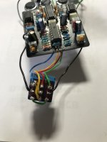
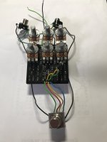
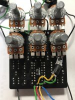
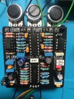
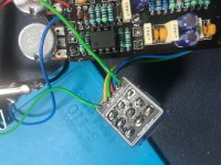
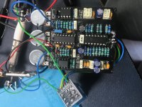
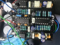
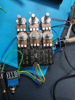
I am hoping that someone has a good eye and can see something stupid I may have done, or point me in a good direction for troubleshooting. Like I said, this is a first build (I know, should have started with something smaller), and the soldering is not that pretty. I've checked the connections as best I can (especially for shorts and continuity), but I'm not sure where I should really be looking. Is there an order for how to debug a board?

Pictures are attached. I can probably try to record the sound if that might be of any help.

I'll keep trying on my own. Should I take everything apart and start again?

Any help would be greatly appreciated.

What a great way to spend an afternoon (or two or three)...

;-)
 

Attachments

  • IMG_6317.jpeg
    IMG_6317.jpeg
    1 MB · Views: 54
  • IMG_6316.jpeg
    IMG_6316.jpeg
    1.3 MB · Views: 48
  • IMG_6315.jpeg
    IMG_6315.jpeg
    1.2 MB · Views: 55
  • IMG_6314.jpeg
    IMG_6314.jpeg
    1.4 MB · Views: 55
A couple things stand out just from visual inspection which chuck will say is the first step. The board could use a little cleaning. You don’t need to have solder on the opposite side of the board but some of your components look like there is less than adequate solder. As fig posted, there are what looks like marks in the pcb from some type of holder maybe?

where is the LED? Why isn’t it in the pad?

your iron may not be hot enough for the type of solder you’re using or the tip could not be good anymore or the right size.

the biggest thing and I literally just made this mistake and was reminded by @music6000 is that your pots are not protected from shorting against the solder side of the board (basically your entire mod section). Tayda sells pots with dust covers on them and you can buy the covers themselves from tayda and other sites too.

someone with better circuit knowledge will have to take over from here. Hope you get it working I know it sucks when it’s not right.

try some way easier pedals to hone your skills. Dark Rift is not what I would call a beginner build.
 
What are you soldering with? Iron as well as solder? and definitely take some IPA and a toothbrush and clean the board, do a good visual inspection starting with those joints you did't think flowed so well, because they didn't
 
Upon further inspection I think you’re not heating the solder pads enough at all. There are a lot of balled up joints instead of nice fillets.
 
Do you have pot covers on the bottom row of pots? I can't tell from your photos.

Also, I don't know if it's a piece of fuzz, a trace, or an errant piece of wire, bit there's something kind of copper colored that looks like it may be shorting two solder joints, just above where the blue wire is connected in the last photo you have of the solder-side of the board.

Cleaning the pcb as others have mentioned will make issues easier to find/rule out.
 
"Last night, I burned up a 9v adapter and overheated a 9V battery before I decided to stop for the day.
I managed to fix the problems with power (did I maybe burn up a component?
"

THIS ☝️ I found most alarming, and seems to have been glossed over since it's "fixed" — what was the problem and how did you fix it?
It may have caused damage, but you're getting signal and the pedal is functioning for the most part.


Just going over what Fig, Barry, Peccary & ADAOCE already noted...


All the chips are oriented correctly, all the polarised caps are oriented correctly, the 78L05 is oriented correctly...

I'm guessing not, because you ordered a kit and are new to the game, but...
Do you have a spare 78L05? — I'd also recommend SOCKETing it, just like the other ICs.
Do you have a spare PT2399 you can swap?


- REPEAT Pot Problem — "goes crazy even with a small turn".
D2, D3 are oriented correctly per the silk-screen on the board, but the doc's board diagram shows both stripes on the side of C7, so that's something to check/clarify — make sure the ground on the diodes is correct to the schematic.
Reflow your solder joints on the Repeat Pot, check for shorts between the pins.
R8 is correct 18k, R10 is correct 1k; C9 is correct, can you verify C7 and C10 are the correct values.
I'd keep going further out from each side of the pot on the schematic, verifying parts values are correct and verifying parts are soldered correctly.
BTW, since I have no idea how much experience you have with delays: it's normal for it to go crazy while turning it, but it should settle down once you stop turning it — this may be something you already know, but if not — there you go.


- MODULATION "All the modulation knows are off in some way"
To clarify, what do you mean "off"? Please describe what each is doing
RATE — Resolder
SHAPE — Needs resoldering
DEPTH — Also resolder

I think Peccary called it... pots may be shorting out momentarily on the back of the PCB. stick a thin bit of cardboard between the pots and board, a bit of a cereal box cut-to-size is usually a good barrier.


- NOISE/CLICKING: "noise and a click with the modulation".
This could be just from the lack of shielding with the circuit not being in its enclosure, and/or running offboard wires too close to the modulation circuitry. Try using shielded wire, especially to/from your jacks, route it well away from the board as much as is possible.

- LED doesn't light
As ADAOCE noted, looks like you've got nothing installed. Do you have de-solder brass-braid and/or a desolder pump? That'll take care of the blocked cathode pad.

- SCRATCHED PCB
If you're using an alligator-clip type PCB holder...

ded96aaeb79ea9fdfbe8bcf3e6328c13.jpg
Or anything similar to this...

... Stick some shrink-tubing over each jaw. That'll protect your PCBs while still providing enough grip within the jaws.


First & foremost, as others already noted...
There are a lot of suspect solder joints, the first thing I'd do is touch up all the joints that look suspect.

solder-problems.jpg


Make sure your tip angle is such that you're heating both the component and pad.

A suggestion: Take out all IC-chips while reworking the solder joints, lest some solder spatters on to an IC and creates a short between pins.

Sorry I can't be of more help than regurgitating what others have already said.
 
Last edited:
First off, a milles mercis ! What a great lot of help here. I'll spend the enxt few hours going over this and get back to everyone. Many thanks for all the advice!
 
  • Like
Reactions: fig
Hello again! The story so far... I took everyone's advice, but ended up with a ruined board. I bought another one and have very carefully put it together. Nothing has blown up or overheated, but I'm still having problems making it work. I'm not a novice at soldering or making. I've gone through all the normal procedures in replacing parts, checking voltages, etc, but I'm clearly missing something.

I also put the project aside for a while and made a few other pedals. They all work. I even added a DIY buffer into a loop pedal. I really thought that this time the project would end nicely.

Compared to the last iteration, I've got less to fix, but have hit a wall and would appreciate your advice. The problem now is that the effects, while present, are nearly inaudible. I strum the guitar and it comes though clearly (and slightly amplified compared to the volume in bypass), then mute the strings and I can hear the effects faintly sounding. My analysis is that this might be from incorrect resistors/capacitors that I've used. I've checked but maybe need this to be proofread?

I double checked everything along the way, or so I thought...

Would there be a process to debug this kind of a problem? Taking out the ICs and testing in some specific order? Probing pertinent spots on the board? Any advice would be greatly appreciated.

In any event, I'll keep working at it.
 

Attachments

  • IMG_6553.jpg
    IMG_6553.jpg
    1.1 MB · Views: 15
  • IMG_6551.jpg
    IMG_6551.jpg
    1 MB · Views: 10
  • IMG_6550.jpg
    IMG_6550.jpg
    1.5 MB · Views: 14
  • IMG_6549.jpeg
    IMG_6549.jpeg
    1.1 MB · Views: 16
Last edited:
Thanks... in fact, C8 was a problem. While triple checking everything, I discovered that C8 was supposed to be 1nf and not 1uf. I fixed that, then I had no sound at all (apart from bypass). I changed out the PT2399 as a last resort before putting the project back on the back burner... and voilà! It works!

Thanks everyone for your help and advice.

Resolved!

Now, on to the next one.
 
I just built one of these and the pt2399 chip had some distortion so I threw a different one in there and it was much better. It’s definitely part of the trouble with those chips. Glad you figured it out. That C8 is very sneaky 1nF hanging out with all those 1uF
 
Back
Top