
PangeaDestructor
Active member
Hey, having some trouble with this one and hoping a fresh pair of eyes will help clear them up. Build doc here, schem on page 2: https://4f3d79f5-cd8b-4c1f-8c04-cc8...d/ff4c6c_4679daada1c24ebd88904170cb24fc95.pdf
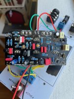
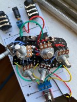
I got it wired up a week ago, and was getting sound but very faint with no effect. After looking at the schematic again, I thought maybe I had the pots wired the wrong way - with lug 3 going to the square hole in the pcb. So I pulled them all out and reinstalled them with lug 1 going to the square hole. Now I get what sounds like a grounding issue. I had the switch and jacks wired to it like this: https://4f3d79f5-cd8b-4c1f-8c04-cc8...d/ff4c6c_5249141a5fe349a2ba9fa52164f37922.pdf (also I used the ground pad that is empty in that diagram just to be safe) but the skinwalker instructions say due to the gain, the bypass input should be grounded, which looks to me like it is(?), so I pulled that off and hooked it up to my testing platform, but I'm still getting just a loud buzzing sound. Twisting the pots does change the character of the buzzing sound, and turning both gains all the way up gives me a faint radio signal. No actual guitar signal coming through now, though. I'm going to try and get at it with the audio probe later.
Now I'm wondering if I had the pots on there correctly the first time, but I think I only have one more chance at re-doing them before I start losing solder pads. I'm using 5457s in lieu of 201s, but the SW page says those work fine and I've never had them be the problem before other than in an AMZ build that sounded off. I know it's hard to see the bottom of the board in that pic because of the pots, but I've completely scrubbed with IPA and reflowed everything (top still has some flux, but i can't see any shorts under magnification on any of them), it looks cleaner than any of my other builds.
Thanks in advance!
Attachments
Last edited: