Designing for a microphone vs guitar input...

Stickman393

Well-known member
Just some questions...

I've been trying to wrap my head around input impedance, but the concept is still pretty abstract and fuzzy to me.

So let's look at an example...schematics at the bottom...

The Roboto, from pedal PCB, has a buffer section before the input of of the HT8950. DC blocking caps...or whatever you might call them...

Alternatively, velleman makes a little DIY kit for a "robot voice changer" that uses the HT8950A. That one uses a tiny board mounted microphone, but only places a resistor and a cap between the mic and the chip input.

My question is...what considerations does a designer take into account when looking at the input source? Is there a reason that one would use a buffer in the guitar input, but not in the mic input? Or did velleman go this route simply to reduce cost and parts count?

Any references to good reading materials would be appreciated...or words of wisdom that help me wrap my head around this...
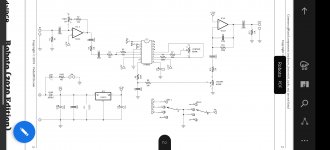
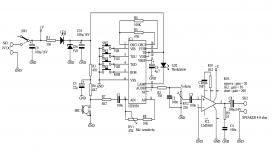
Screenshot_20211004-131817__01.jpg voice-modulation-circuit-ht8950.png
 
Here's a pretty good read...the author seems to know their stuff..;)
 
So I struggled (and still do) with this concept as well. Let's start with this analogy from Zachary Vex, which helped me:

"Here's the basic idea: You get on a bicycle, and try to bike up a hill. You are completely frustrated; the pedals will hardly turn & you can't get enough speed to get any balance. What's wrong?

Well in this case, you are the source (driving the bike) and the bike's input impedance is controlled by the gears - and it's set to such a high gear that it's input impedance is too low for you to drive it. Your output impedance has to do with the muscles & tendons in your legs, if they were tougher (meaning lower impedance output) it would match the bike. How do you fix it? Raise the input impedance of the bike by lowering the gear ratio. Suddenly, you can go, balance, and are happily climbing the hill.

Every source (guitar, signal generator, preamp's output, output of a pedal) has a limit to how much resistance it can drive without buckling under the stress. The input impedance of whatever it is driving has to be equal or higher to the source's output impedance (most people set it ~10 times higher for good measure) or else you'll hear degradation of the signal.

Low impedances require a lot of drive current - i.e. thick muscles & heavy bones are required. High impedances can be driven by skinny legs. Low impedance inputs are like tenth gear, high input impedances are like first. Impedance is almost the same as resistance, and in many cases measures almost exactly the same as the apparent input resistance. But the word impedance lets us include the possibility that the resistance changes with frequency (pitch), so that capacitances & inductances can be included, since so many circuits include these devices.

FETs are high input impedance devices because they hardly require any input current to drive them all the way on or off. They are extremely sensitive. They will detect the static on a comb from several inches away if you put a wire on the gate and dangle it in the air!"
 
This post from Chuck gets at a key concept for working with impedances in electronic circuits: the voltage divider. This was a BIG breakthrough for my understanding of impedance, but is only half the story. For the sake of simplicity, I'm going to ignore the reactive components of inductors & capacitors for now, but they are cannot be ignored - especially with the complex impedances that guitar pickups present. But I think this is a good starting point:

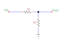
If we use resistance in place of impedance the output resistance of your source can be thought of as R1 in a voltage divider, and the input resistance of your load (input to an opamp in this case) as R2 in the voltage divider.

Voltage Divider.png

If your source (R1) is quite high output resistance at 100k, and your load (R2) has the same value value for input resistance, then from this formula:

Example 1: Vout = Vin*(R2/R1+R2) -> Vin*(100k/200k) -> Vout = 0.5*Vin

If our source is a 100mV guitar signal, then we only end up with a 50mV signal on the other end! We've lost half of it due to the voltage divider formed by our 100k source output resistance and 100k load input resistance.

If we change our load input resistance to 1M (1000k), then we end up with less guitar signal being lost to ground:

Example 2: Vout = Vin*(R1/R1+R2) -> Vin*(1000k/1100k) -> Vout = 0.91*Vin

We now get 91mV out of our 100mV signal, instead of 50mV. A big improvement! This ~90% value is part of the reason why we strive to have an input resistance of at least 10x the value of our output impedance - anything less than that and we're just throwing away a big chunk of that signal to ground.

Now let's go back to calling it impedance, but still ignore the reactive components (apologies to every EE in the room):
In the case of the robot voice changer, our guitar source has a pretty high-impedance output signal (100k let's say), so it needs an even higher input impedance - at least 10x that, so ~1M. I don't see an input impedance on the HT8950 datasheet, but most non-FET input opamps don't support the high input impedance we need. So it's probably safe to assume a guitar signal would end up like Example 1, and we would lose a lot of signal due to the pickup being "loaded down" by the HT8950s not-super-high input impedance. If we add a dedicated high impedance input stage like in the Roboto, our guitar will make it through with much of the signal left intact, like Example 2. That same high impedance input stage can, as an opamp, support a MUCH lower output impedance - as low as 600ohms. That's perfect for interfacing with the unknown input impedance of our HT8950.

I don't know much about that microphone, but from the schematic, we can assume it has a much lower output impedance compared to our guitar. Low enough that the amount of signal lost to the voltage divider is acceptable. Maybe someone else can jump in on the typical specs of a microphone like that.

Now that just explains the DC resistance component of our signal, but most circuits use coupling capacitors, and we mentioned that our guitar pickup & cable have inherent capacitance & inductance elements. What do you get when you combine resistors and capacitors with AC signals? RC filters...

Chuck's first comment is a great starting point for that.
 
Back
Top